Method for interpreting dipping natural fracture and fault planes identified from borehole images

a technology of fracture and fault plane, which is applied in the field of interpreting specific dipping surfaces from borehole images, can solve problems such as the possibility of fracture or fault that is not apparent using one imaging technology, and may not be apparen

Inactive Publication Date: 2011-03-17
TASK FRONTERRA GEOSCI
View PDF11 Cites 19 Cited by
  • Summary
  • Abstract
  • Description
  • Claims
  • Application Information

AI Technical Summary

Problems solved by technology

However, a fracture or fault that is not apparent using one imaging technology may, or may not, be apparent in another.

Method used


Image

  • Method for interpreting dipping natural fracture and fault planes identified from borehole images
  • Method for interpreting dipping natural fracture and fault planes identified from borehole images
  • Method for interpreting dipping natural fracture and fault planes identified from borehole images

Examples


Embodiment Construction

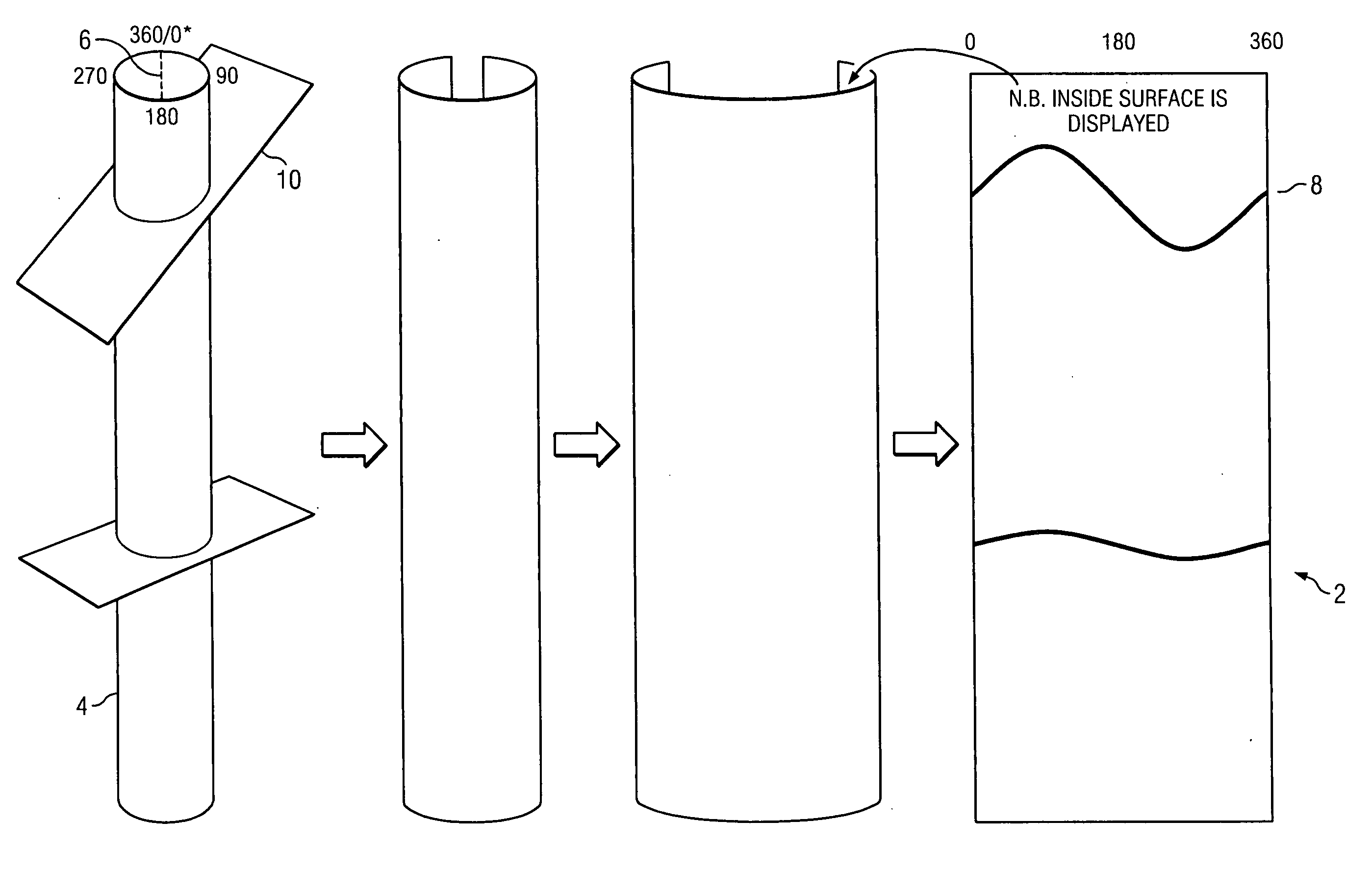
[0027]In general, the present invention addresses the issue of operator objectivity / subjectivity by creating a consistent method of reference to dipping fracture and fault planes identified in borehole images. It, therefore, also provides a consistent framework for the interpretation of those features identified. For the purposes of borehole image interpretation, a fault is defined as a planar, or near planar, feature that shows offset (i.e., throw) that is greater than the borehole diameter (i.e., typically ranging between 4.5 inches and 21 inches in diameter).

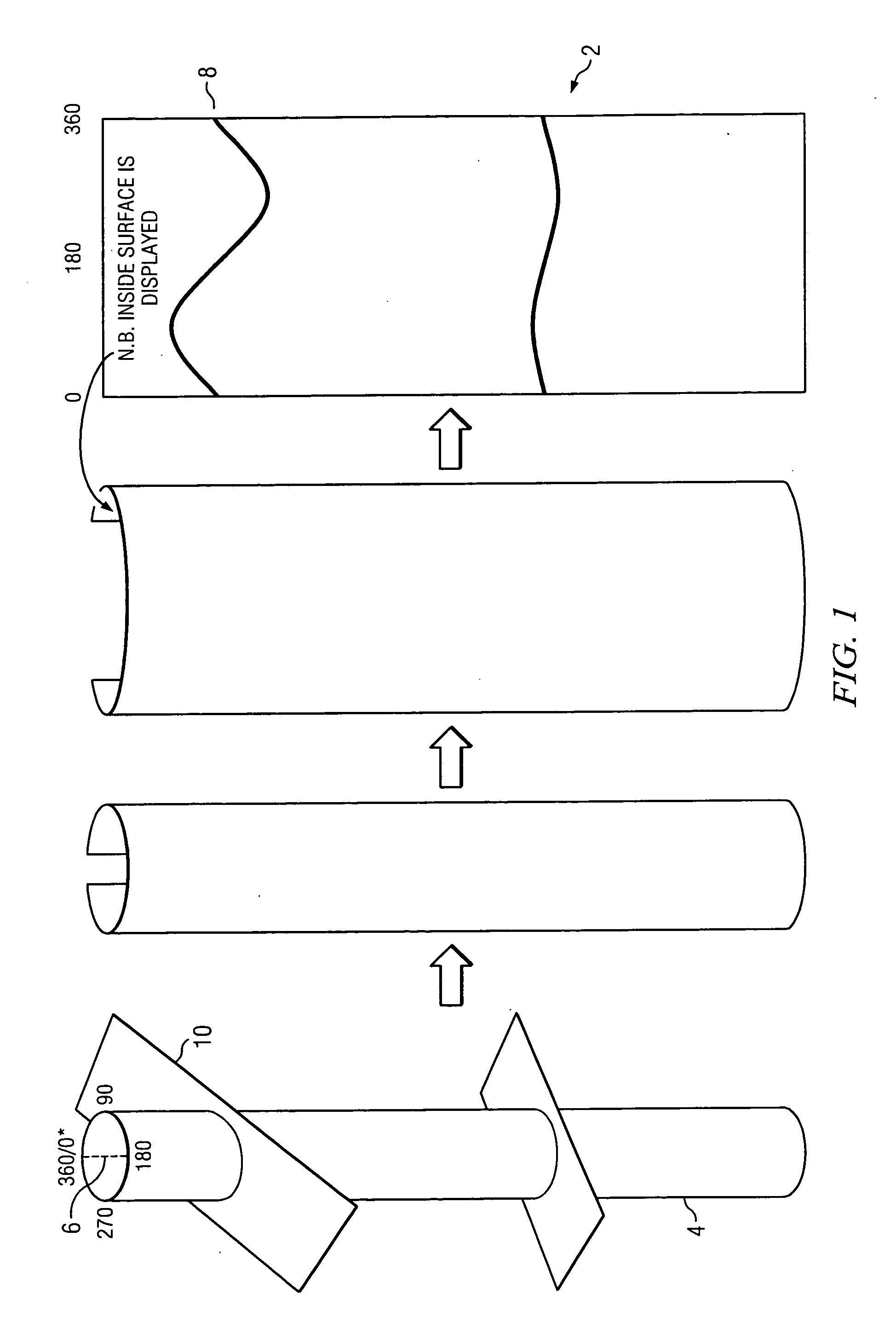
[0028]As is shown in FIG. 1, a display of borehole images 2, which is obtained from a cylindrical borehole 4, most commonly presents a two-dimensional representation of the inner surface of the borehole with reference to geographic or true north 6, or in the case of highly angled boreholes, to the borehole highside. The dotted line represents true north, or in the case of a highly inclined or horizontal borehole 14, the boreh...


PUM


Abstract

A method of interpreting specific dipping surfaces in earth formations, namely, fracture and fault planes from borehole images. The method is applicable to borehole images obtained from any borehole imaging tool, regardless of tool physics or acquisition type. The interpretation method provides for detailed description of feature s in order to provide a robust framework for subsequent interpretation work.

Description

CROSS-REFERENCE TO RELATED APPLICATION[0001]This application claims priority to U.S. Provisional Patent Application Ser. No. 61 / 276,690, filed Sep. 14, 2009, for “Method for Interpreting Dipping Natural Fracture and Fault Planes Identified From Boreholes.”TECHNICAL FIELD[0002]This invention relates to a method of interpreting specific dipping surfaces from borehole images. In particular, the invention relates to an improved method of interpreting faults and fractures from borehole images. The method may be applied to images obtained from any borehole imaging tool regardless of tool physics or acquisition type.BACKGROUND OF THE INVENTION[0003]Various methods have been used to interpret specific dipping surfaces, namely, faults and fractures. These interpretation methods are applied to images obtained from various borehole imaging tools. Examples of the available tool technology and potential sources for such tools includes, but is not limited to: wireline technology, such as resistiv...

Claims


Application Information

Patent Timeline
Patent Type & Authority Applications(United States)
IPC IPC(8): G06K9/00
CPCG01V1/50G01V2210/642G01V3/20G01V2210/74G01V2210/646
Inventor DUNCAN, ANDREW R.HUSTEDT, JENS KLAUSHOMANN, HERMANN JOSEFBORELL, JARRETLOPEZ, RAMIRO GABRIEL
Owner TASK FRONTERRA GEOSCI
Why Eureka
Try Eureka