
Heating air mat and air mat heating system having the same

Inactive Publication Date: 2011-03-24
LEE DONG CHUL
View PDF2 Cites 9 Cited by
  • Summary
  • Abstract
  • Description
  • Claims
  • Application Information

AI Technical Summary

Benefits of technology

[0011]Another aspect of the invention is to provide a heating air mat and an air mat heating system including the same, which discharges heated air outside the mat to increase heating efficiency.
[0016]According to the embodiments of the invention, the heating air mat provides heat to a user by supplying heated air into the air mat, thereby eliminating accidents relating to the use of electricity while ensuring good heating efficiency and reduction of energy consumption when used for local heating and assistant heating.

Problems solved by technology

However, both the boiler heating type and the electric heating type heat the room by heating the bottom of the room and thus have low heating efficiency in view of bed users.
In other words, since a person lying on a bed is separated a predetermined distance from the bottom of the room, these heating types have low thermal efficiency with respect to the body of the person and consume lots of energy by heating the entire bottom of the room to thereby providing low heating efficiency.
Although an electric mattress, an electric blanket, an electric heat mat, or the like is used for local heating or assistant heating, these have problems such as a short circuit of an electric wire, a complicated manufacturing process, high manufacturing costs, and the like.
Particularly, when using any of these local heating or assistant heating articles, a user directly contacts a heat generating member of the article and is influenced by electromagnetic waves emitted therefrom which are not good for the user's health.
Further, a heating method of the electric mattress and the like using the electric wire provides a temperature variation on the surface thereof, which can cause scalding of a user approaching or contacting the electric wire and can provide an unpleasant feeling to the user when using the electric mattress and the like for a long time.
Moreover, when using the electric mattress as the assistant heating article by laying the electric mattress under a bed mattress, the surface of the bed mattress is liable to be discolored by the electric wire of the electric mattress.

Method used


Image

  • Heating air mat and air mat heating system having the same
  • Heating air mat and air mat heating system having the same
  • Heating air mat and air mat heating system having the same

Examples


Embodiment Construction

[0024]Exemplary embodiments of the invention will hereinafter be described in detail with reference to the accompanying drawings. In the detailed description of the embodiments, like components will be denoted by like reference numerals and a repetitious description thereof will be omitted herein.

[0025]First, a heating air mat in accordance with a first embodiment of the present invention and an air mat heating system including the same will be described with reference to FIGS. 1 to 4.

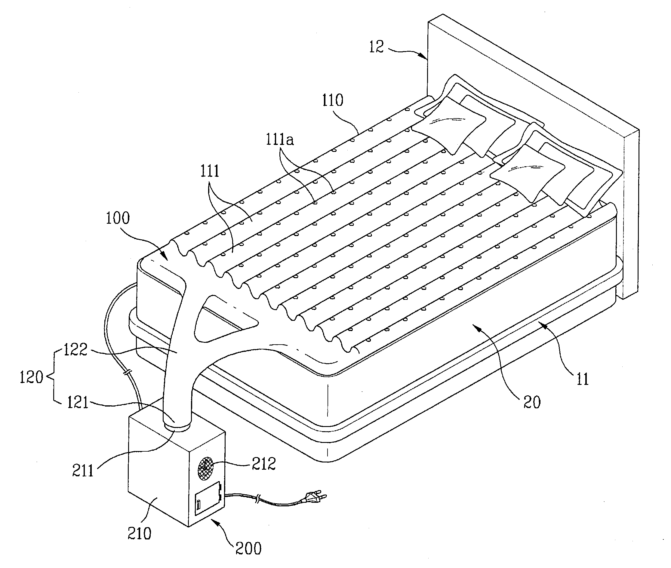
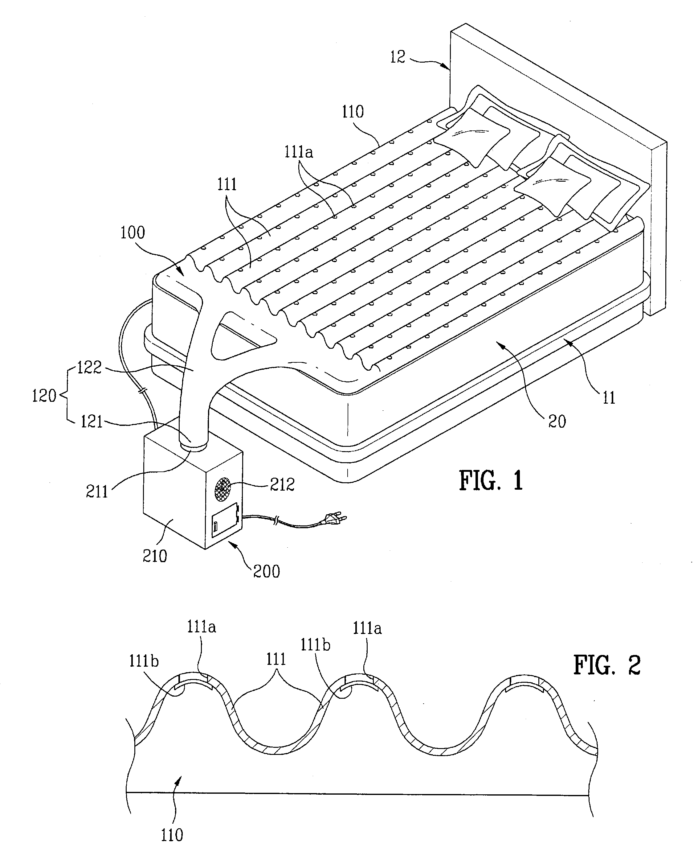
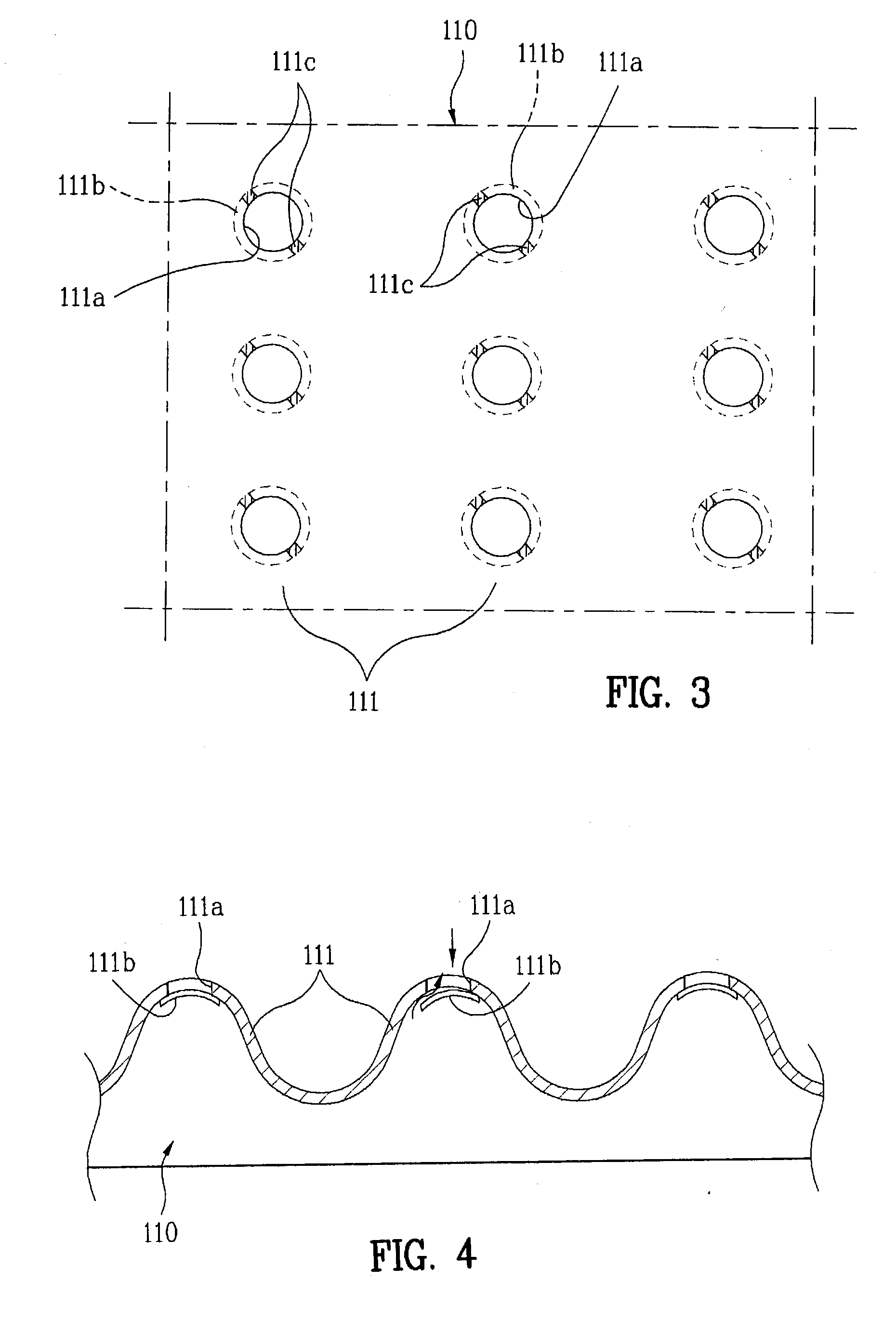
[0026]FIG. 1 is a perspective view of an air mat heating system including a heating air mat disposed on a bed in accordance with a first embodiment of the invention, FIG. 2 is a cross-sectional view of the heating air mat shown in FIG. 1, FIG. 3 is a plan view of the heating air mat in accordance with the first embodiment of the invention, and FIG. 4 is a cross-sectional view of the heating air mat, in accordance with the first embodiment of the invention, including a heated air discharge port through ...


PUM


Abstract

A heating air mat which supplies heated air into the mat to provide heat to a user, and an air mat heating system including the same are disclosed. The air mat heating system includes a heating air mat having a mat body and a heated air injection part through which the heated air is injected into the mat body, and a heater connected to the heated air injection part of the air mat to supply the heated air into the air mat. The air mat provides heat to the body of a user by supplying heated air into the air mat, thereby eliminating accidents relating to the use of electricity while ensuring good heating efficiency and to reduction of energy consumption when used for local heating and assistant heating.

Description

BACKGROUND OF THE INVENTION[0001]1. Field of the Invention[0002]The present invention relates to a heating air mat and an air mat heating system including the same and, more particularly, to a heating air mat and an air mat heating system including the same that supplies heated air into the mat to provide heat to a user.[0003]2. Description of the Related Art[0004]A typical indoor heating apparatus is generally classified into a boiler heating type and an electric heating type. In the boiler heating type, water heated by a boiler is supplied to and circulated through a heating pipe arranged on the bottom of a building, thereby heating the bottom of an indoor room.[0005]In the electric heating type, heating is performed in two manners, that is, a bottom heating manner and an air conditioner manner. In the bottom heating manner, a heating pipe having a liquid heat storage medium and a heat generating wire on a panel is buried in the bottom of the room and electric energy is supplied t...

Claims


Application Information

Patent Timeline
IPC IPC(8): A47C27/08A47C31/00
CPCA47C27/082A47C21/048A47C21/04A47C27/08F25D5/02
Inventor LEE, DONG-CHUL
Owner LEE DONG CHUL
Features
  • Generate Ideas
  • Intellectual Property
  • Life Sciences
  • Materials
  • Tech Scout
  • Unparalleled Data Quality
  • Higher Quality Content
  • 60% Fewer Hallucinations
Learn More