Breather with independent inlet/outlet flow paths

a flow path and filtration technology, applied in the direction of fluid couplings, couplings, braking systems, etc., can solve the problems of raising environmental and cleanliness issues, affecting creating pressure and vacuum inside, so as to improve the protection of hydraulic systems, reduce the amount of oil exhaust, and increase the filtration capacity

Active Publication Date: 2011-03-24
PARKER INTANGIBLES LLC
View PDF18 Cites 15 Cited by
  • Summary
  • Abstract
  • Description
  • Claims
  • Application Information

AI Technical Summary

Benefits of technology

[0006]The present invention provides an apparatus and method for filtering fluid in a breather assembly and providing uncontaminated fluid to and from a reservoir. The breather allows in-take fluid traveling through a first flow path to be filtered before entering the reservoir through a first directional valve. The breather also allows exha

Problems solved by technology

These hydraulic systems often create pressures and vacuums within the tank or reservoir during use.
As can be appreciated, such vents are subject to degradation and wear over time.
In addition, vent gases can include oil vapor, which raise environmental and cleanliness issues if allowed to escape freely.
Further, when a breather becomes saturated with reservoir vapor, the syst

Method used


Image

  • Breather with independent inlet/outlet flow paths
  • Breather with independent inlet/outlet flow paths
  • Breather with independent inlet/outlet flow paths

Examples


Embodiment Construction

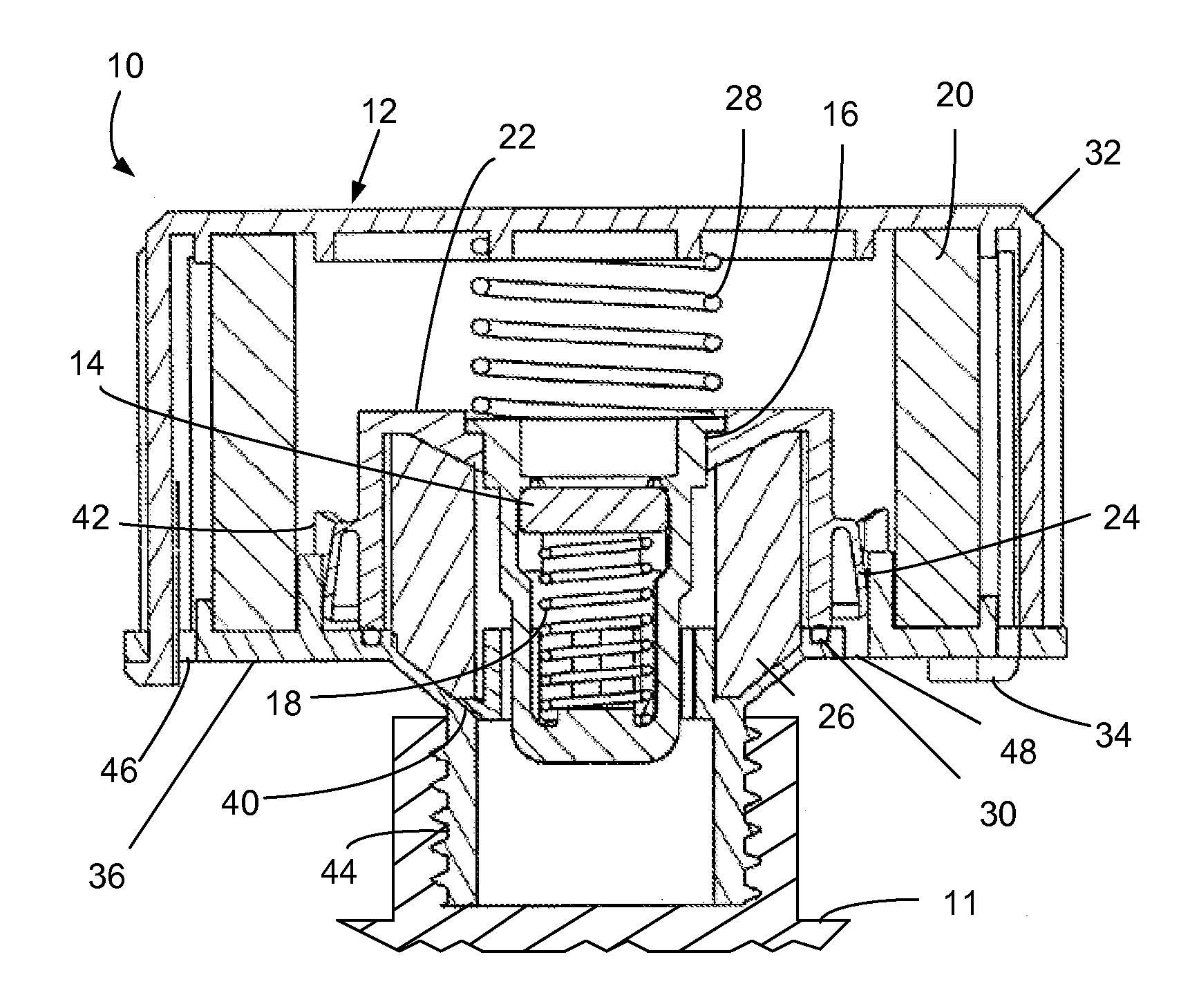
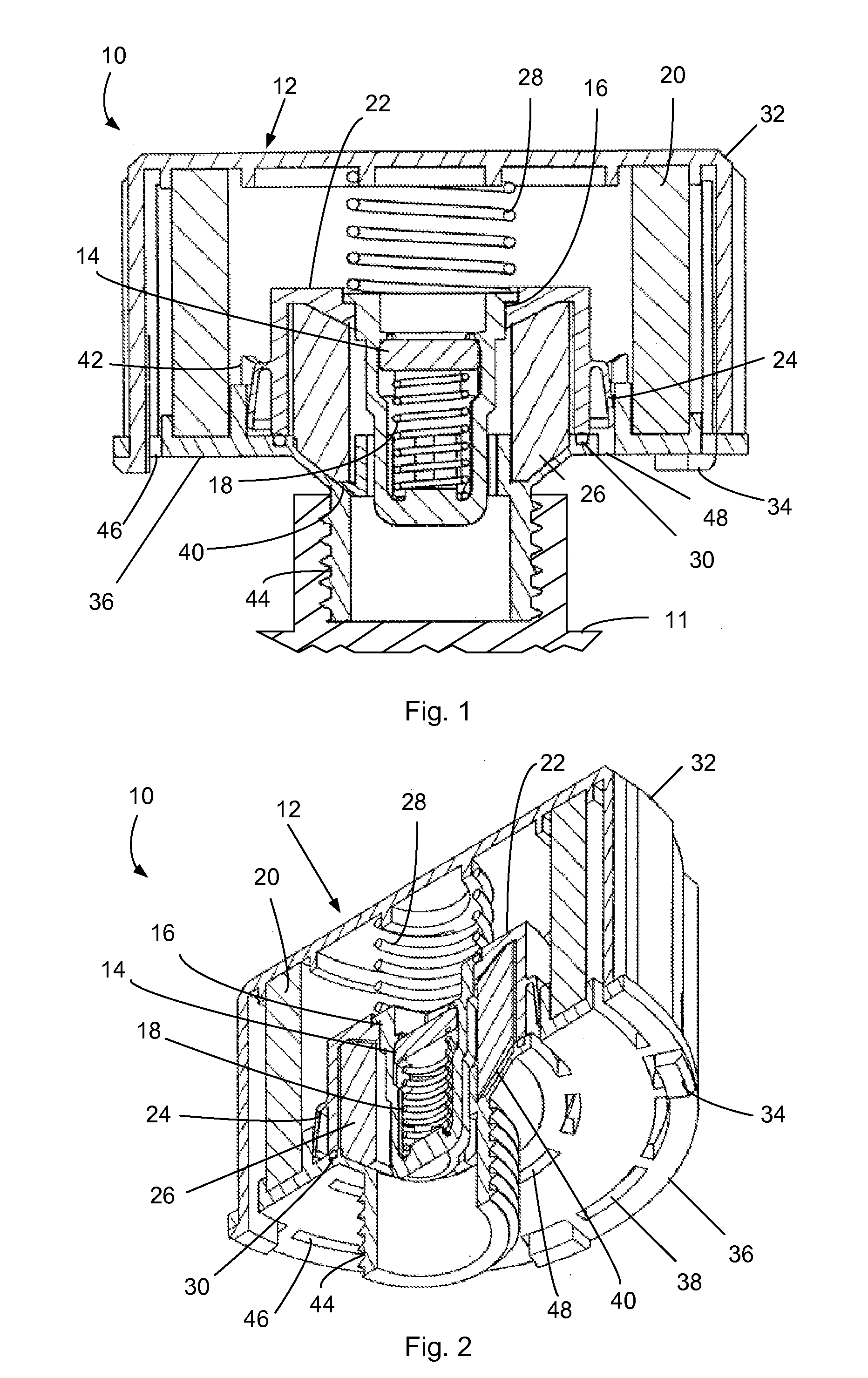
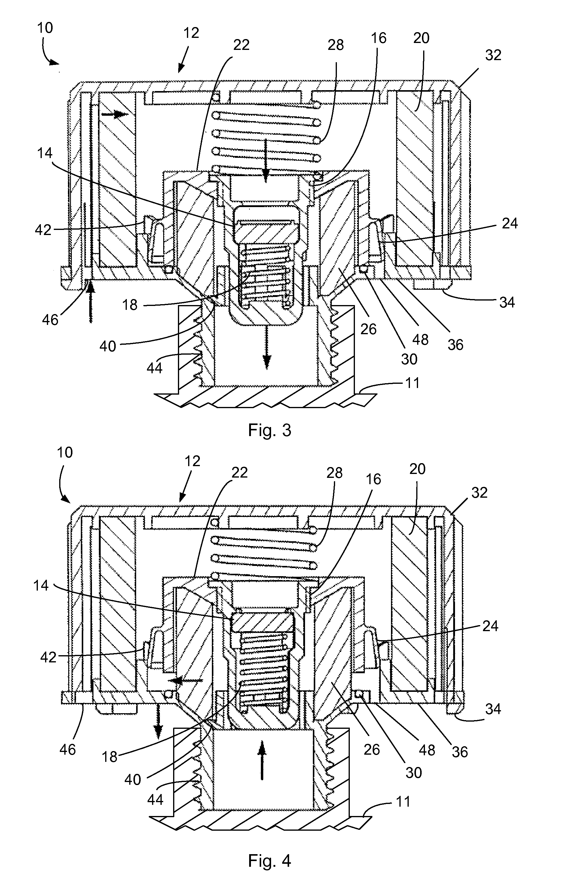
[0022]Referring now to the drawings in detail, and initially to FIGS. 1, 2 and 7, an exemplary breather assembly according to the invention is indicated generally by reference numeral 10. The breather assembly 10 can be used in hydraulic systems, such as in industrial and mobile equipment, or in other fluid transfer systems, to provide uncontaminated fluid, in particular a gas, into the systems. The breather assembly 10 can also be used to prevent oil mist from escaping the systems and to provide a charge pressure on the reservoir of the systems. The breather assembly 10 generally includes a housing 12 that encloses a first directional valve 14 and a second directional valve 22, a filtration / separation device 20 disposed in a first flow path, and a second flow path. These major components as well as other components of the device can be made of any suitable material, such as, for example, a polymer material such as nylon or polypropylene, metals, etc.

[0023]The first and second direc...


PUM


Abstract

The present invention provides an apparatus and method for filtering fluid in a breather assembly and providing uncontaminated fluid to a reservoir. The breather allows in-take fluid traveling through a first flow path to be filtered before entering the reservoir through a first directional valve. The breather also allows exhaust fluid traveling through a second flow path, separate from the first flow path, to exit through a second directional valve.

Description

RELATED APPLICATIONS[0001]This application claims the benefit of U.S. Provisional Application No. 61 / 054,862 filed May 21, 2008, which is hereby incorporated herein by reference.FIELD OF INVENTION[0002]The present invention relates generally to fluid filtration, and more particularly to a breather for fluid filtration in a fluid system.BACKGROUND[0003]Certain hydraulic systems, such as those found in mobile fluid power applications, include a tank or reservoir that receives and stores hydraulic fluid. These hydraulic systems often create pressures and vacuums within the tank or reservoir during use. Breather vents are typically provided in the tank to ensure that uncontaminated air is provided into the system and that the proper pressures are maintained for efficient and safe operation of the system. These vents allow air to enter the tank or reservoir when the pressure is low, and allow air to be expelled from the tank or reservoir when the pressure is high.[0004]As can be apprecia...

Claims


Application Information

Patent Timeline
IPC IPC(8): B60T17/18B60T11/26
CPCB60T11/26F16K17/196B60T17/222B60T17/06Y10T137/7976Y10T137/8085
Inventor CELLA, ALBERT F.GEMBOLIS, DONALD J.TROTT, JOHN A.
Owner PARKER INTANGIBLES LLC
Why Eureka
Try Eureka