Inverted pendulum type vehicle

a technology of pendulum and vehicle, which is applied in the direction of bicycles, cycle equipment, chairs, etc., can solve the problems that the occupant may have difficulty in controlling the direction of the vehicle movement,

Active Publication Date: 2011-03-24
HONDA MOTOR CO LTD
View PDF6 Cites 23 Cited by
  • Summary
  • Abstract
  • Description
  • Claims
  • Application Information

AI Technical Summary

Benefits of technology

[0011]The downward inclination of the seat surfaces toward the center of the vehicle urges the buttocks of the vehicle occupant to be urged toward the center of the vehicle, and this also promotes the gravitational center of the vehicle occupant to be placed in the center of the vehicle at all times.

Problems solved by technology

In particular, when the seat is constructed such that the vehicle occupant cannot readily change the sitting position, the vehicle occupant may have some difficulty in controlling the direction of the movement of the vehicle.

Method used


Image

  • Inverted pendulum type vehicle
  • Inverted pendulum type vehicle
  • Inverted pendulum type vehicle

Examples


first embodiment

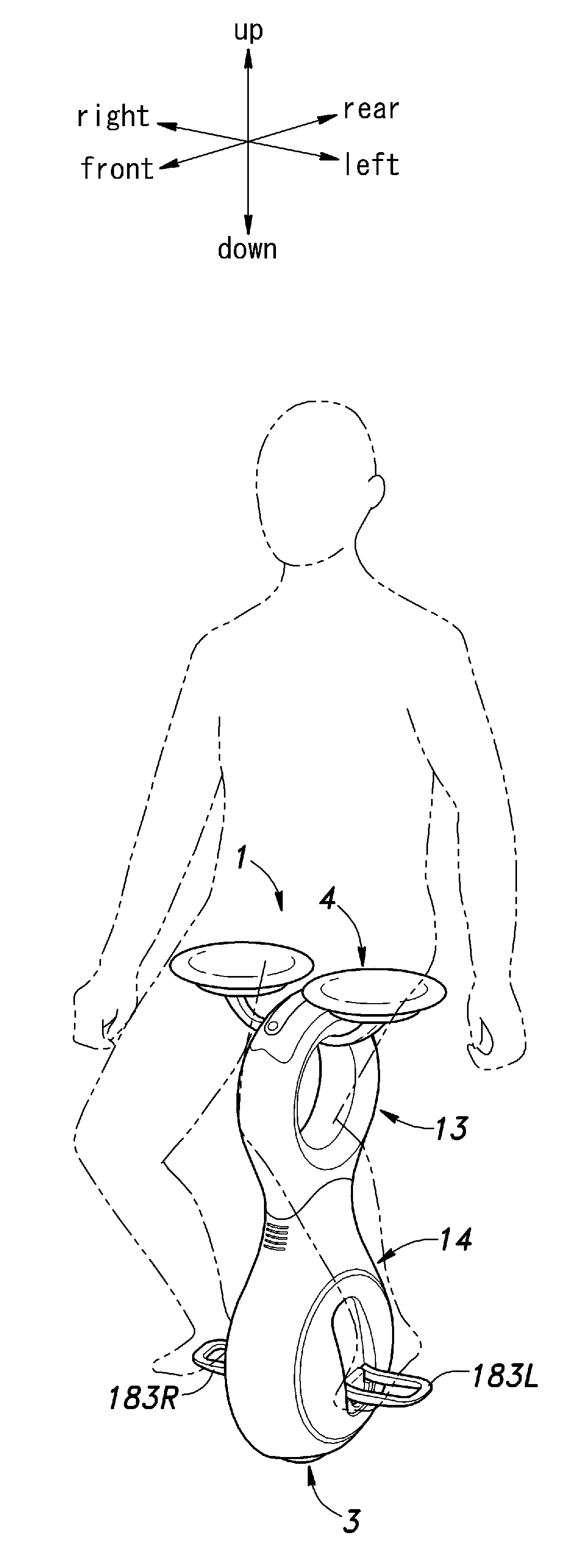
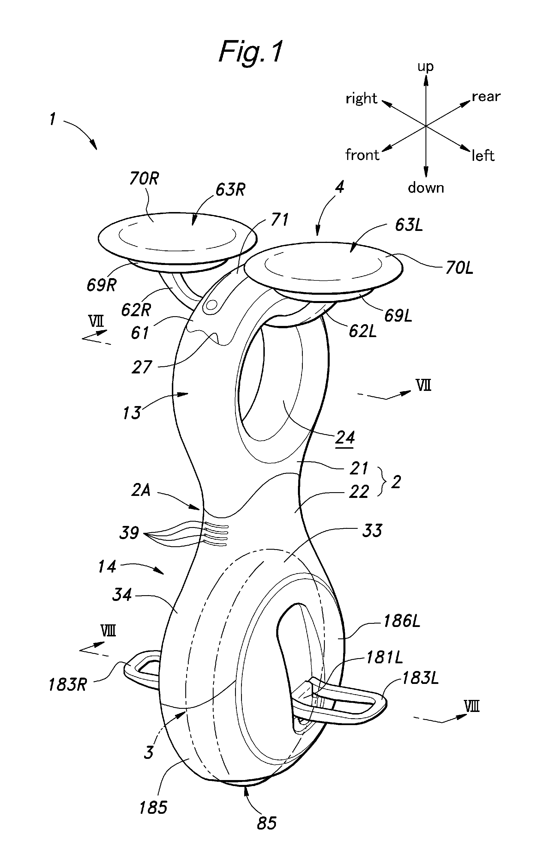
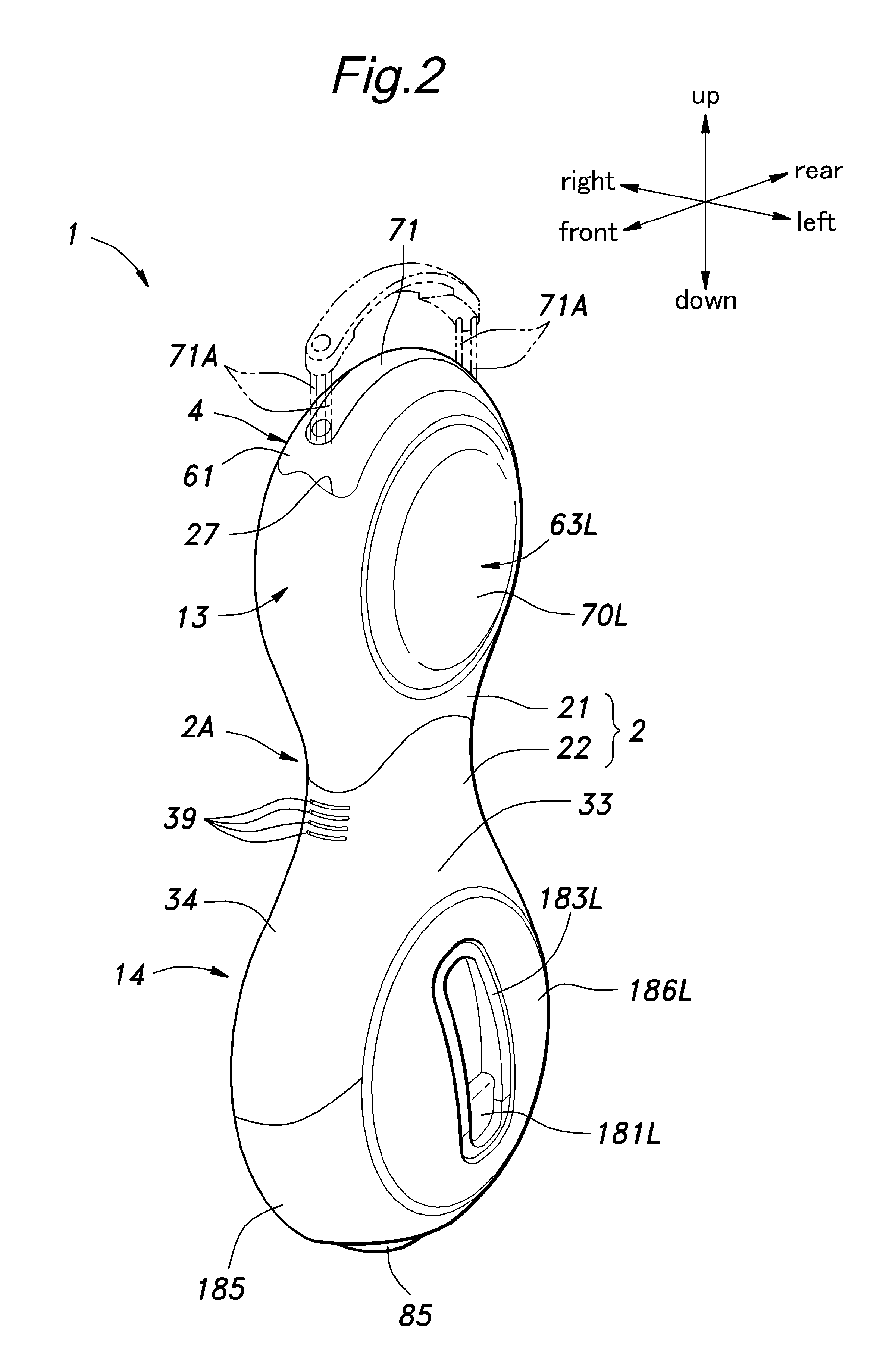
[0030]Referring to FIGS. 1 to 5, the inverted pendulum type vehicle 1 given as the present invention comprises a frame 2 elongated in a vertical direction, a drive unit 3 incorporated in a lower part of the frame 2, a seat assembly 4 incorporated in an upper part of the frame 2, an electric unit 11 received in an inner middle part of the frame 2 and a battery unit 10 received in an upper part of the frame 2 to power the drive unit 3 and electric unit 11 as well as various sensors. The electric unit 11 comprises an inverted pendulum control unit 5, an upper load sensor 6 and an inclination sensor 7. The control unit 5 controls the drive unit 3 according to the principle of the inverted pendulum control based on output signals received from various sensors so as to maintain the vehicle 1 in an upright posture. The sensors include a pair of step load sensors 8 and rotary encoders 9.

[0031]Referring to FIG. 1, the frame 2 is formed as a hollow shell, and have a substantially greater fore...

second embodiment

[0105]As shown in FIG. 15, the seat assembly 400 of the second embodiment comprises a pair of saddle members 63 and a pair of four-bar linkage mechanisms 401 each using grounded links (407, 408) of unequal lengths and supporting the corresponding saddle member 63.

[0106]As the two four-bar linkage mechanisms 401 are symmetric to each other, only one of them is described in the following. The four-bar linkage mechanism 401 comprises a first pivot shaft 405, a second pivot shaft 406, and upper arm 407, a lower arm 408 and a saddle post 409.

[0107]The first pivot shaft 405 consists of a hollow shaft member extending in the fore and aft direction, and is supported at two axial ends thereof by the base member 410 which is placed into the upper space 26C from the upper opening 27 of the upper frame 21. The upper wall of the base member 410 closes the upper opening 27 with the peripheral edge of the upper wall engaging the peripheral wall surrounding the upper opening 27, and fixedly secured...


PUM


Abstract

In a vehicle (1) including a frame (2) incorporated with a drive unit (3) for enabling the frame to travel in a prescribed direction and a seat assembly (4) supported by the frame and including a pair of saddle members (63) defining a pair of seat surfaces (70A), respectively, configured to jointly support buttocks of a vehicle occupant, the saddle members are resiliently supported by the frame in such a manner that the seat surface of each saddle member is in an approximately horizontal orientation but is progressively tilted inward with a downward movement of the saddle member under a load of a vehicle occupant. Thus, one of the saddle members receiving a greater load than the other tilts downward toward the center of the vehicle, and this causes the vehicle occupant to be urged toward the saddle member receiving a smaller load so that the vehicle occupant is automatically urged toward the center of the vehicle, and hence the gravitational center of the vehicle occupant may be placed in the center of the vehicle at all times.

Description

TECHNICAL FIELD[0001]The present invention relates to a vehicle provided with a pair of saddle members defining a pair of seat surfaces, respectively, configured to jointly support buttocks of a vehicle occupant, and in particular to an inverted pendulum type vehicle provided with such saddle members which is capable of traveling in both a fore and aft direction and a lateral direction while maintaining an upright orientation, and in particular to a seat assembly suitable for such a vehicle.BACKGROUND OF THE INVENTION[0002]Known is an inverted pendulum type vehicle or an omni-directional vehicle comprising a pair of drive assemblies individually actuated by electric motors and a main wheel held between the drive assemblies and frictionally driven by the drive assemblies. See WO2008132779A1 (US20100096905A1) for instance. Each drive assembly comprises a drive disk coaxially opposing the drive disk of the other drive assembly and a plurality of drive rollers obliquely arranged along t...

Claims


Application Information

Patent Timeline
Patent Type & Authority Applications(United States)
IPC IPC(8): B62D61/00
CPCB62K3/007B62K1/00B62K11/007
Inventor WAITA, HIRONORIHAMAYA, KAZUSHIGOMI, HIROSHI
Owner HONDA MOTOR CO LTD
Why Eureka
Try Eureka