Metal plate member fixation device

a technology for fixing devices and metal plates, which is applied in the direction of fastening means, screws, threaded fasteners, etc., can solve the problems of wasting time and labor, complex mounting and dismounting procedures of moving plate members, and high processing costs, so as to facilitate installation, minimize the height (length) of the spring member, and present the disconnection between components

Inactive Publication Date: 2011-03-24
WANG KUO CHUNG
View PDF13 Cites 8 Cited by
  • Summary
  • Abstract
  • Description
  • Claims
  • Application Information

AI Technical Summary

Benefits of technology

[0008]The present invention has been accomplished under the circumstances in view. It is therefore an object of the present invention to provide a metal plate member fixation device for joining metal plate members, which facilitates installation and presents disconnection between component parts.
[0009]To achieve these and other objects of the present invention, a metal plate member fixation device comprises a barrel for bonding to a first metal plate member, a locking device, which comprises a lock screw bolt axially slidably coupled to the barrel for inserting through a mounting through hole on the first metal plate member and threading into a screw hole on a second metal plate member to lock the first metal plate member and the second metal plate member together and a cap affixed to the head of the lock screw bolt for gripping, a spring member sleeved onto the shank of the lock screw bolt inside the cap and stopped against the head of the lock screw bolt, and a stop washer set in an annular inside locating groove inside the barrel around the shank of the lock screw bolt and stopped against the other end of the spring member for stopping against one end of the thread of the lock screw bolt to prohibit escape of the lock screw bolt of the locking device from the barrel. By means of the application of the stop washer, the height (length) of the spring member can be minimized so that the metal plate member fixation device can have a low profile characteristic for easy, quick and accurate installation.

Problems solved by technology

This movable plate member mounting and dismounting procedure is complicated, wasting much time and labor.
This processing process requires high precision and wastes time and labor.
During processing, the cap may be compressed excessively, resulting in permanent deformation.

Method used


Image

  • Metal plate member fixation device
  • Metal plate member fixation device
  • Metal plate member fixation device

Examples


Embodiment Construction

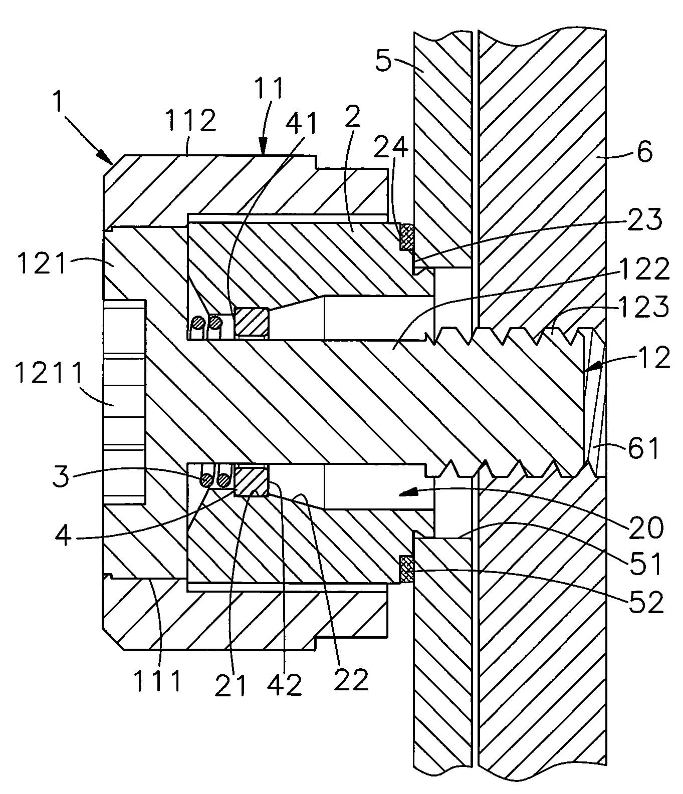
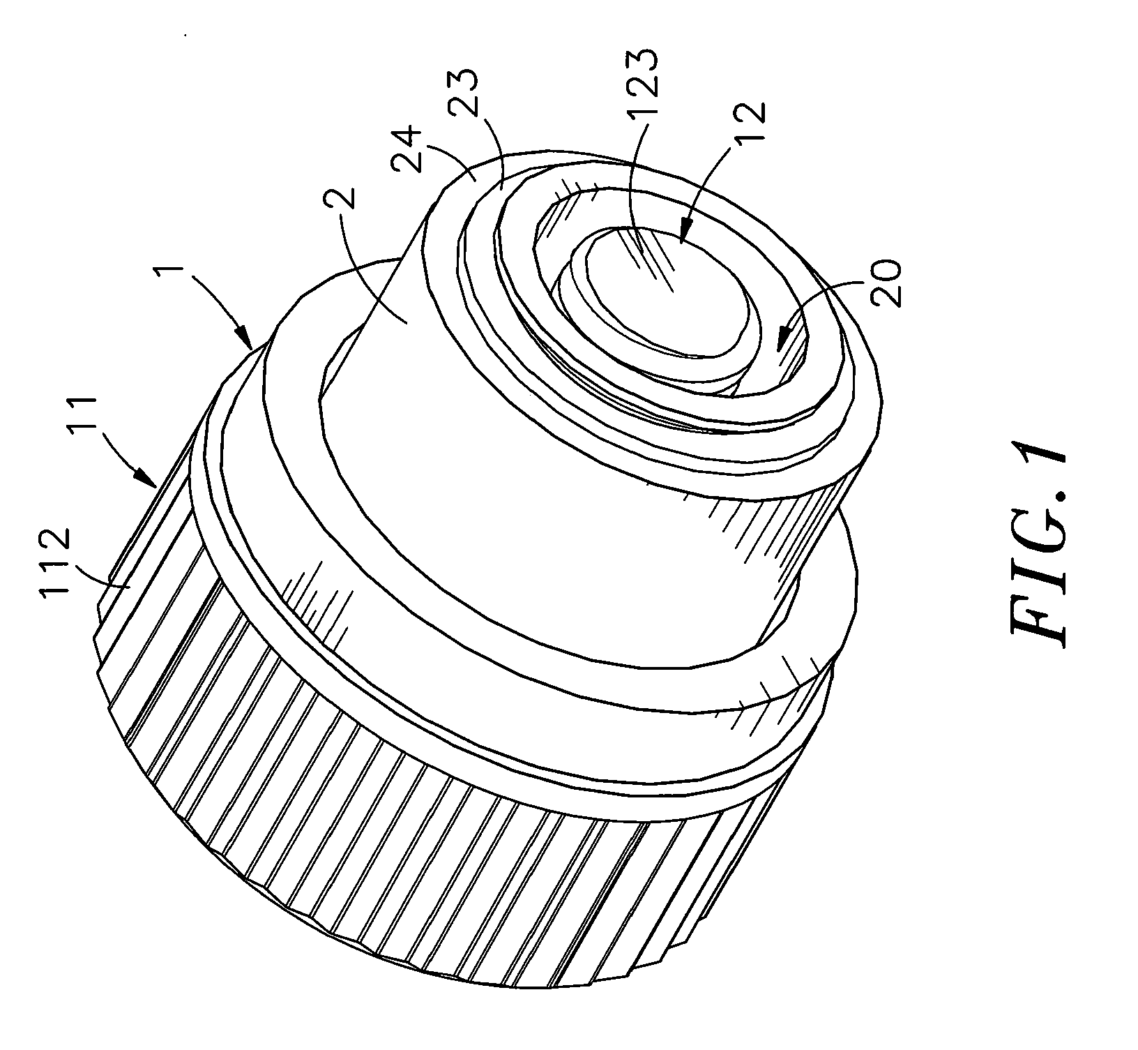
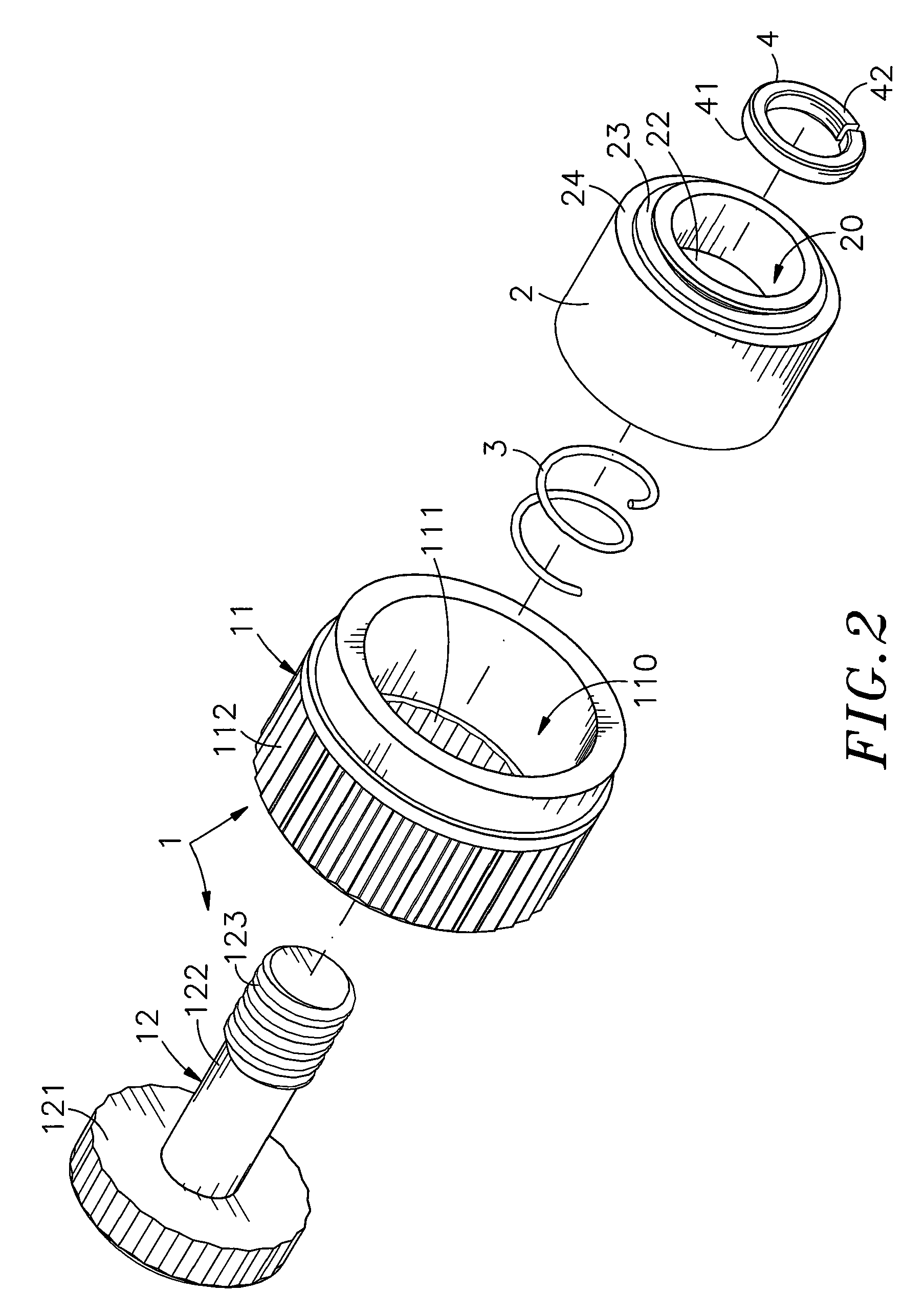
[0018]Referring to FIGS. 1˜4, a metal plate member fixation device in accordance with the present invention is shown comprising a locking device 1, a barrel 2, a spring member 3, and a stop washer 4.

[0019]The locking device 1 comprises a cap 11 and a lock screw bolt 12. The cap 11 is a hollow member having a center opening 110 axially extending through the top and bottom sides for receiving the barrel 2, the lock screw bolt 12 and the spring member 3, a mounting groove 111 extending around the inside wall thereof in one end of the center opening 110 and a grip 112 located on the periphery for gripping by hand. The lock screw bolt 12 is a metal screw bolt having a head 121 fitting the mounting groove 111 of the cap 11, a shank 122 perpendicularly extended from the center of the bottom wall of the head 121, a thread 123 spirally extending around the periphery of one end of the shank 122 remote from the head 121 and a tool groove 1211 located on the top wall of the head 121.

[0020]The b...


PUM


Abstract

A metal plate member fixation device includes a barrel for bonding to a mounting through hole of a first metal plate member, a lock screw bolt inserted through the barrel for threading into a screw hole of a second metal plate member to lock the first and second metal plate members together, a cap affixed to the head of the lock screw bolt for gripping, a spring member sleeved onto the shank of the lock screw bolt and stopped against the heat of the lock screw bolt, and a stop washer positioned in an annular inside locating groove in the barrel around the shank of the lock screw bolt and stopped against the other end of the spring member for allowing axial movement of the lock screw bolt relative to the barrel within a predetermined range and for stopping against one end of the thread of the lock screw bolt to prohibit escape of the lock screw bolt from the barrel.

Description

BACKGROUND OF THE INVENTION[0001]1. Field of the Invention[0002]The present invention relates to a metal plate member fixation device for joining two metal plate members and more particularly, to a low-profile metal plate member fixation device, which is formed of a locking device, a barrel, a spring member and a stop washer, wherein the stop washer secures the lock screw bolt of the locking device to the barrel, allowing axial movement of the lock screw bolt relative to the barrel within a predetermined range and prohibiting escape of the lock screw bolt from the barrel.[0003]2. Description of the Related Art[0004]When fastening two plate members together, a positioning screw formed of a knob, a ring and a screw nail is usually used. During installation, the screw nail and the ring are secured to the first plate member, and then the knob is rotated to drive the screw nail into the second plate member, and then a hand tool is used to fasten tight the screw nail, affixing the first a...

Claims


Application Information

Patent Timeline
Patent Type & Authority Applications(United States)
IPC IPC(8): F16B39/10
CPCF16B5/0208
Inventor WANG, KUO-CHUNG
Owner WANG KUO CHUNG
Why Eureka
Try Eureka