
Prosthetic Socket Liner

a technology of prosthetic sockets and sockets, applied in the field of vacuum liner, can solve the problems of amputees that cannot use the known system, size, weight, difficulty in use,

Active Publication Date: 2011-03-24
SRT PROSTHETICS & ORTHOTICS LLC +1
View PDF3 Cites 67 Cited by
  • Summary
  • Abstract
  • Description
  • Claims
  • Application Information

AI Technical Summary

Problems solved by technology

Use of suction sockets on below knee amputees was not initially practical.
Among the disadvantages of known systems are size, weight, and difficulty of use.
There are many amputees that cannot use known system because of size (particularly smaller adults and children), age of the patient, and length of the stump.
For many patients, the time-consuming steps and cumbersome strap systems involved in using known prostheses cause the patients to eschew prostheses entirely.
Further, known sockets are subject to unhygienic conditions, as they collect perspiration from the residual limb, and bacteria and other contaminants from the ambient air surrounding the prosthesis.

Method used


Image

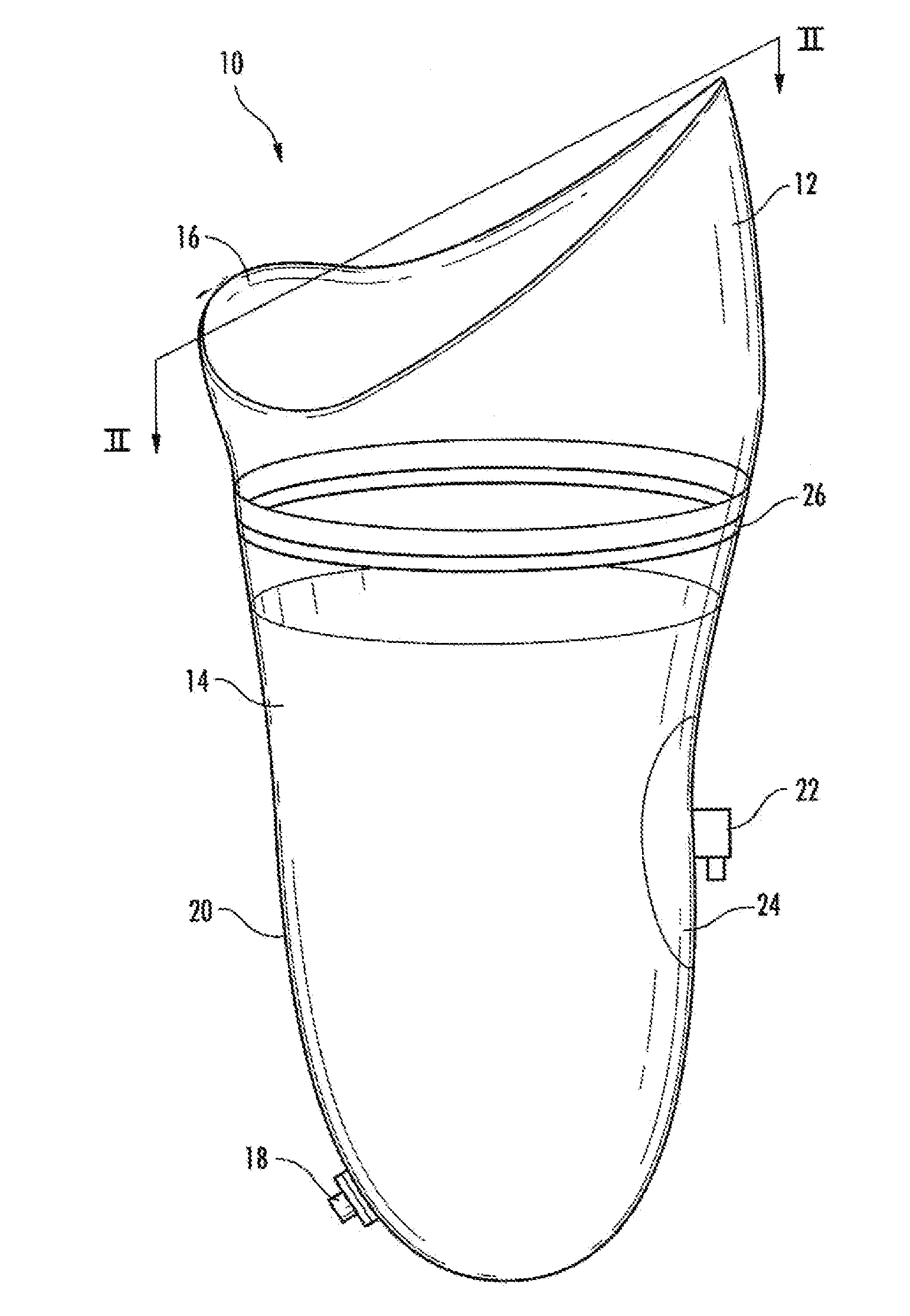
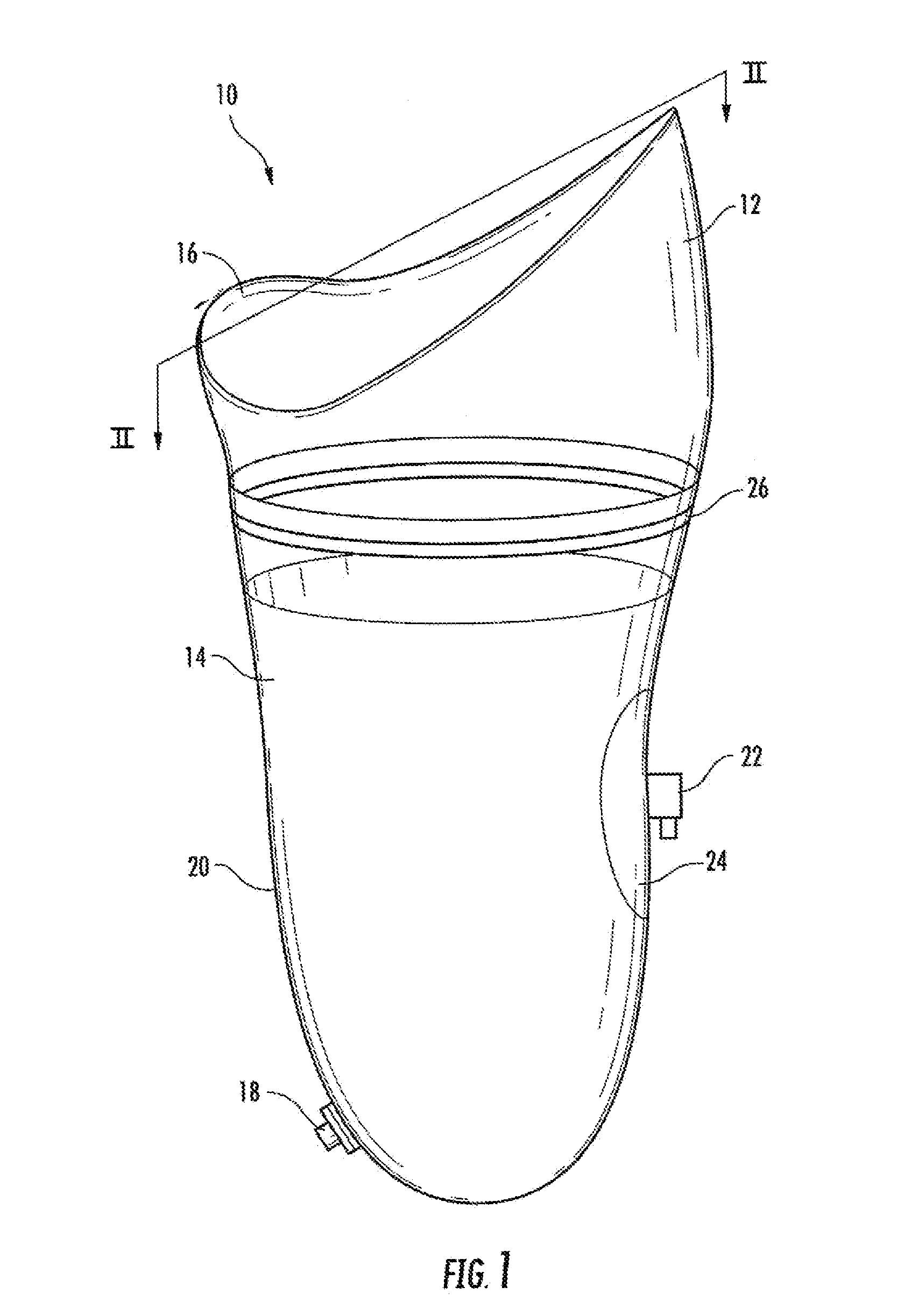
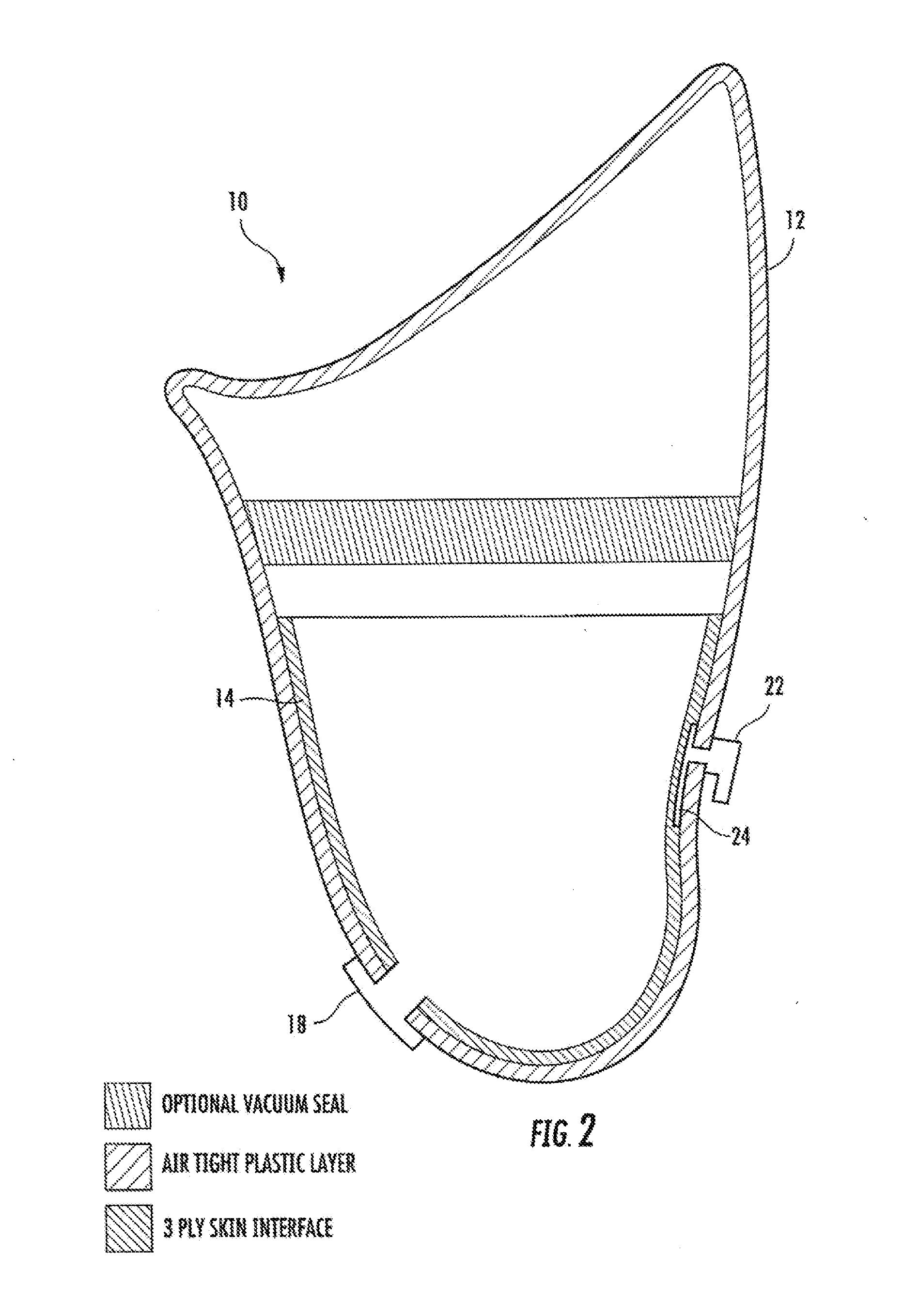
  • Prosthetic Socket Liner
  • Prosthetic Socket Liner
  • Prosthetic Socket Liner

Examples


Embodiment Construction

[0034]In the following description, specific details are set forth in order to provide a thorough understanding of the invention. However, it will be apparent that the invention may be practiced without these specific details.

[0035]While this invention has been described in connection with the best mode presently contemplated by the inventor for carrying out his invention, the preferred embodiments described and shown are for purposes of illustration only, and are not to be construed as constituting any limitations of the invention. Modifications will be obvious to those skilled in the art, and all modifications that do not depart from the spirit of the invention are intended to be included within the scope of the appended claims. Those skilled in the art will appreciate that the conception upon which this disclosure is based, may readily be utilized as a basis for the designing of other structures, methods and systems for carrying out the several purposes of the present invention. ...


PUM


Abstract

A removable liner used in conjunction with a socket for a prosthetic device, in which a vacuum is wicked across the entire area of a porous fabric of the liner, is disclosed. The liner preferably includes a shaped-layer made from one of either a silicone or a urethane and has an exterior surface, an interior surface and a passage therein which opens at each of the two surfaces and connects to a valve of the socket. The liner further includes a first porous fabric covering at least a portion of the exterior surface of the shaped-layer including the corresponding opening of the passage, and a second porous fabric covering at least a portion of the interior surface of the shaped-layer including the corresponding opening of the passage. A vacuum source coupled to the liner, via the valve on the socket, draws a vacuum which is wicked across the entire surface of the first and second porous fabrics which interface with the socket and the user's residual limb, respectively. The vacuum secures the socket to the liner and the liner to the residual limb of the user.

Description

RELATED APPLICATIONS[0001]This application is a continuation-in-part and claims the priority of co-pending U.S. application Ser. No. 12 / 586,235, titled “Prosthetic Socket” and filed on Sep. 18, 2009. The present application also incorporates by reference the disclosures of U.S. application Ser. Nos. 11 / 640,150, filed Dec. 14, 2006, 12 / 286,474, filed Sep. 30, 2008, and 61 / 192,386, filed Sep. 9, 2008.TECHNICAL FIELD OF THE INVENTION[0002]The present device relates to vacuum liner used in a socket assembly for a prosthetic device. In particular, the present device relates to a vacuum-mapped liner which resides within a socket assembly having an outer shell and an air barb communicating with the liner on the interior of the socket and for connection to an exterior vacuum source.BACKGROUND OF THE INVENTION[0003]The history of artificial limbs goes back to very remote times. In fact, there is some evidence that the Romans and the Greeks may have improvised some sort of substitute for limb...

Claims


Application Information

Patent Timeline
Patent Type & Authority Applications(United States)
IPC IPC(8): A61F2/80
CPCA61F2/7812A61F2002/805A61F2/80
Inventor MCKINNEY, DONALD RAY
Owner SRT PROSTHETICS & ORTHOTICS LLC
Learn More