
Terminal Identification Method, Authentication Method, Authentication System, Server, Terminal, Wireless Base Station, Program, and Recording Medium

a technology of authentication system and identification method, applied in the field of identification method, can solve the problems of insufficient consideration of privacy protection, difficult inferring value of a(k, i1), and insufficient consideration of s(k, i), so as to ensure privacy protection, eliminate the need of encryption, and ensure the effect of wireless bandwidth

Active Publication Date: 2011-03-24
NIPPON TELEGRAPH & TELEPHONE CORP
View PDF19 Cites 34 Cited by
  • Summary
  • Abstract
  • Description
  • Claims
  • Application Information

AI Technical Summary

Benefits of technology

This approach ensures unique terminal identification, reduces wireless bandwidth usage, eliminates the need for encryption, and decreases the computational burden on wireless terminals, while maintaining privacy and security.

Problems solved by technology

However, no consideration has been paid to the protection of privacy.
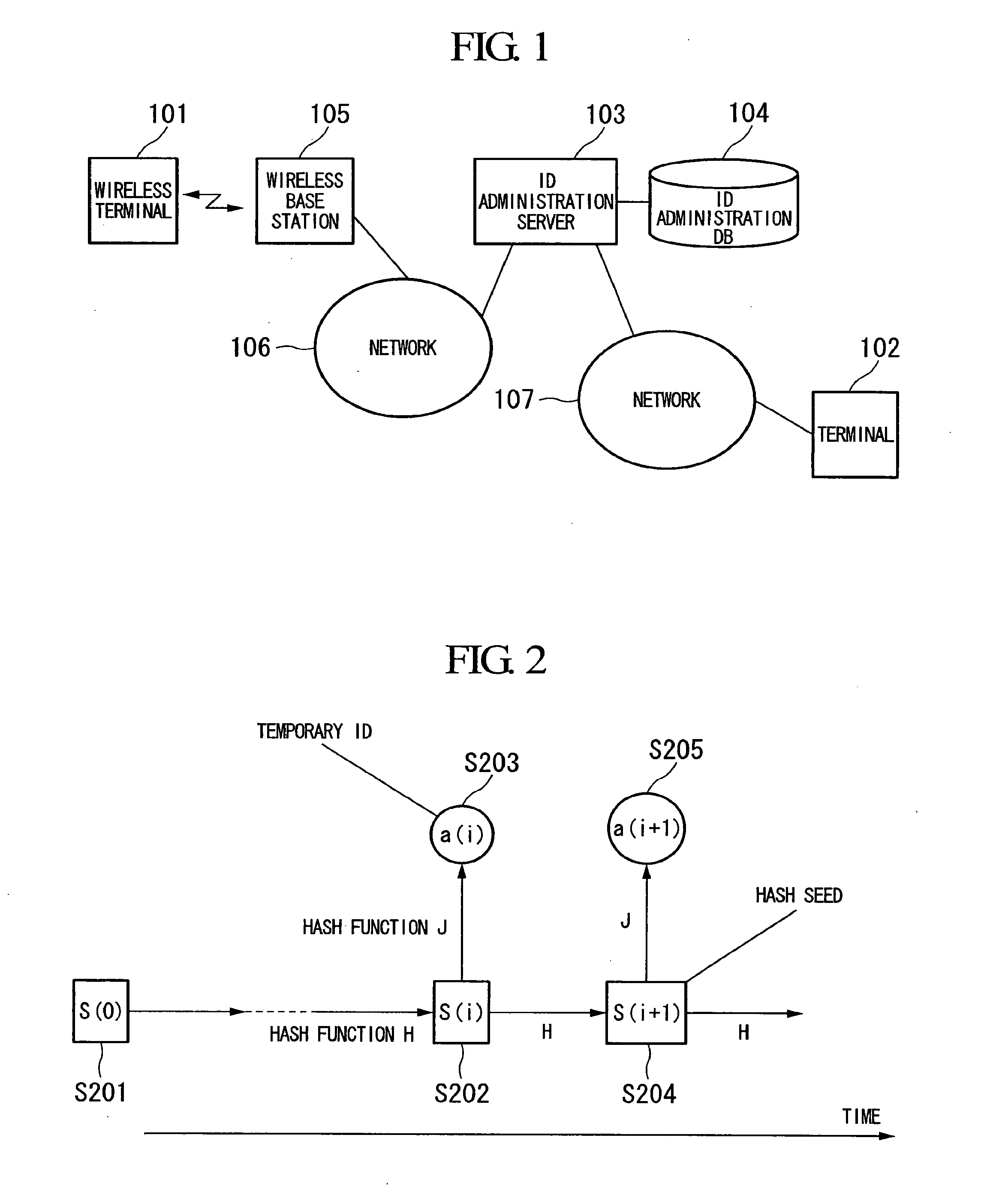
This scheme has such a feature that deleting the information of S(k, 0) and S(k, i−1) from a memory at the tag makes it difficult to infer the value of a(k, i−1) from the value of a(k, 0) of the past, even if S(k, i) can be obtained from the discarded tag.
This feature takes advantage of the fact that inverse calculation is difficult for hash function H. Moreover, because inverse calculation is difficult for hash function J, it is also difficult to infer the value of S(k, i) from the value of a(k, i) that has been sent out, thus it is difficult to infer a(k, i+1) which is used next.

Method used


Image

  • Terminal Identification Method, Authentication Method, Authentication System, Server, Terminal, Wireless Base Station, Program, and Recording Medium
  • Terminal Identification Method, Authentication Method, Authentication System, Server, Terminal, Wireless Base Station, Program, and Recording Medium
  • Terminal Identification Method, Authentication Method, Authentication System, Server, Terminal, Wireless Base Station, Program, and Recording Medium

Examples


first embodiment

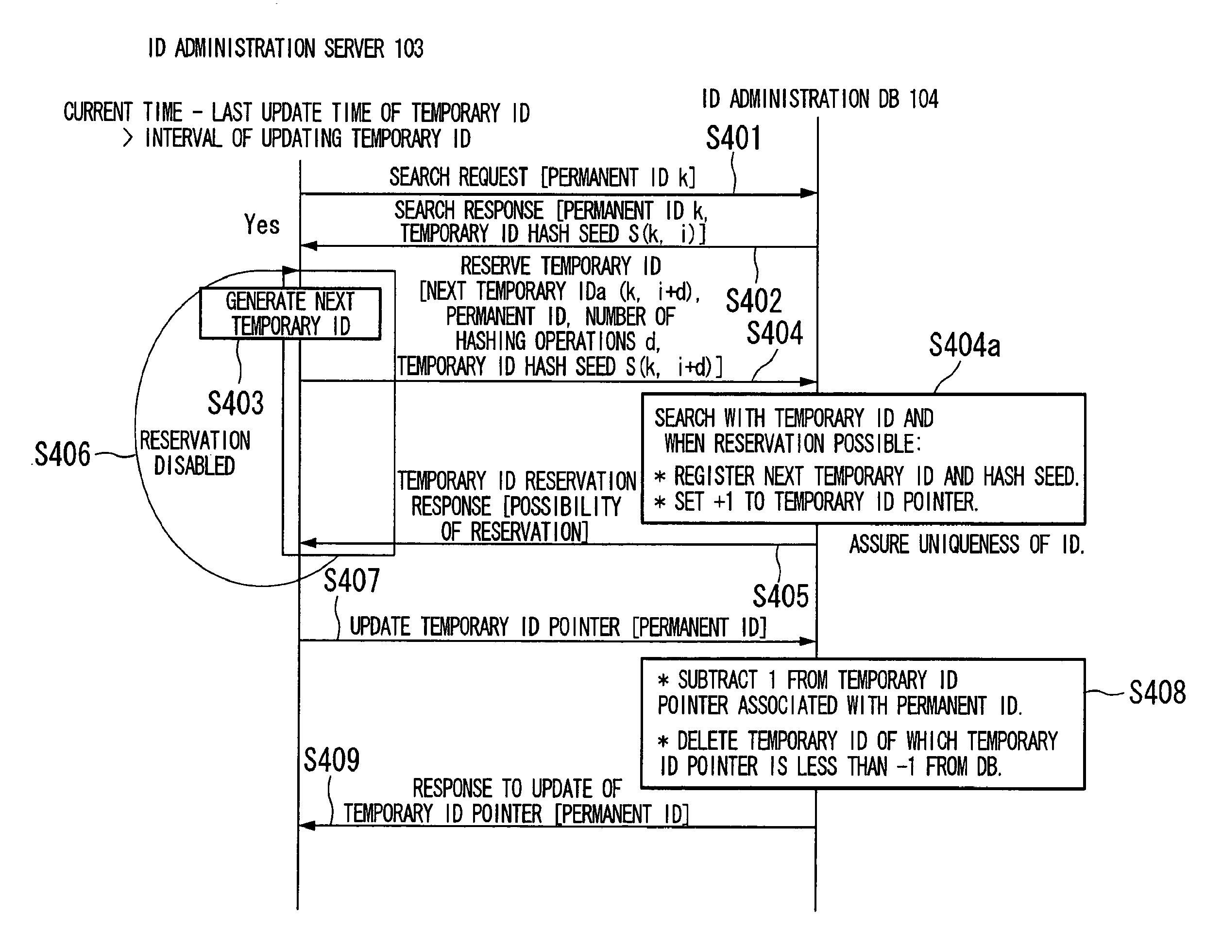
[0116]First, key points of this embodiment will be described. Assume two-way communication between a wireless terminal and a NW. In order to mutually carry out integrated authentication, an ID administration server calculates the value of increment d (an integer equal to or larger than 0) of i (an integer equal to or larger than 0) which represents the version of ID, along with NW authentication information. The ID administration server stores the increment d in an ID administration DB (database) (temporary ID reservation of the embodiment to be described later) and notifies it to the wireless terminal (a terminal authentication response of the embodiment to be described later), so that the value of i is incremented by d in both the wireless terminal and the ID administration server (storage in the ID administration server is the ID administration DB), with S(k, i) of the wireless terminal and S(k, i) of the ID administration server always be synchronized.

[0117]The increment d of i ...

second embodiment

[0166]Next, a second embodiment of the present invention will now be described. FIG. 10 is a block diagram schematically showing the constitution of a system which authenticates wireless terminal according to this embodiment. The authentication system includes a wireless terminal 1101, a wireless base station 1102, an authentication administration server 1103, an authentication administration database 1104, and a network 1105.

[0167]The wireless terminal 1101 is connected to the network 1105 via the wireless base station 1102 and the authentication administration server 1103, and is capable of communicating with another terminal or a server (omitted in the drawing) connected to the network 1105. Moreover, the wireless terminal 1101 carries out mutual authentication with the authentication administration server 1103 and, upon completion of the mutual authentication, makes communication with the network 1105 via the authentication administration server 1103. Each wireless terminal 1101...

third embodiment

[0295]FIG. 18 is a block diagram showing the constitution of a system according to this embodiment. A wireless terminal 2001 has the function of the wireless terminal 101 of the first embodiment and the function of the wireless terminal 1101 of the second embodiment. A wireless base station 2002 has the function of the wireless base station 105 of the first embodiment and the function of the wireless base station 1102 of the second embodiment. An ID & authentication administration server 2003 has the function of the ID administration server 103 of the first embodiment and the function of the authentication administration server 1103 of the second embodiment. An ID administration database 2004, an authentication administration database2005, and a terminal 2006 have functions similar to those of the ID administration database 104 of the first embodiment, the authentication administration database 1104 of the second embodiment, and the terminal 102 of the first embodiment, respectively...


PUM


Abstract

A terminal identification method is provided which enables two-way communications between terminals and a network while identifying terminal IDs and protecting privacy. Also, authentication method and system are provided which require no complicated calculating process, less steps and smaller amount for wireless communications, and less power consumption. A server and terminal share a hash function and an initial value determined for each terminal, calculate the same temporary ID by hashing the initial value the same number of times with the hash function, and identify the terminal using the calculated temporary ID. The server and the terminal also hold a common hash function and authentication information, acquire an authenticating communication parameter from communication parameters temporarily common during communication, and generate an authentication key using the authentication information, the authenticating communication parameter, and the hash function. Then at least one of the server and terminal performs authentication using the generated authentication key.

Description

TECHNICAL FIELD[0001]The present invention relates to a terminal identification method used in RFID (radio frequency identification) or the like which is required to provide protection of privacy. The present invention relates also to an authentication method employed between a wireless terminal and a server used in ubiquitous networking and network security.[0002]Priority is claimed on Japanese Patent Application No. 2005-364522 filed on Dec. 19, 2005 and Japanese Patent Application No. 2006-127546 filed on May 1, 2006, the contents of which are incorporated herein by reference.BACKGROUND ART[0003]“Ubiquitous” is a buzz word in recent years. The word “ubiquitous” means an information system which allows it to use computers and network to, for example, acquire the status of a person or an object so as to monitor the overall situation of the place, or provide information pertinent to the circumstances.[0004]What plays an important role in the ubiquitous is a sensor network. The senso...

Claims


Application Information

Patent Timeline
Patent Type & Authority Applications(United States)
IPC IPC(8): G06F15/177G06F21/44G06F21/62G06F21/73
CPCH04L9/3236H04L9/3273Y02B60/50H04L2209/805H04W12/06H04L63/0869H04W12/02H04W12/75
Inventor TAKASUGI, KOICHIMITANI, KOKISAITO, HIROSHI
Owner NIPPON TELEGRAPH & TELEPHONE CORP
Learn More