Electronic Component Mounting Apparatus, Component Supply Apparatus, and Electronic Component Mounting Method

a technology for electronic components and supply apparatuses, which is applied in metal working apparatus, manufacturing tools, printed circuit manufacture, etc., can solve the problems of no other alternative component supply apparatus, and the inability to completely prevent the wrong insertion operation of component supply tapes, so as to reduce the wrong insertion operation of supply tapes, and ensure the effect of reliability

Active Publication Date: 2011-03-31
YAMAHA MOTOR CO LTD
View PDF7 Cites 27 Cited by
  • Summary
  • Abstract
  • Description
  • Claims
  • Application Information

AI Technical Summary

Benefits of technology

[0017]According to the invention, it is possible to provide an electronic component mounting apparatus, a component supply apparatus, and an electronic component mounting method with high reliability capable of reducing wrong insertion operations of supply tape.
[0018]According to the invention, it is possible to provide an electronic component mounting apparatus, a component supply apparatus, and an electronic component mounting method capable of reducing wrong insertion operations of supply tape and supplying new electronic component tape at a high operation rate.

Problems solved by technology

Even after the bar code data is collated, it might be impossible to completely prevent wrong insertion operations of the component supply tape such as mounting the component supply tape on an unintended component supply apparatus or placing the component supply apparatus on an unintended component supply cart.
There may be a case where the supply tape runs out of electronic components while mounted on the printed board and no other alternative component supply apparatus is available.
In such a case, a solution might require a complicated operation of connecting a new supply tape to the back end of the supply tape running out of electronic components.

Method used


Image

  • Electronic Component Mounting Apparatus, Component Supply Apparatus, and Electronic Component Mounting Method
  • Electronic Component Mounting Apparatus, Component Supply Apparatus, and Electronic Component Mounting Method
  • Electronic Component Mounting Apparatus, Component Supply Apparatus, and Electronic Component Mounting Method

Examples


Embodiment Construction

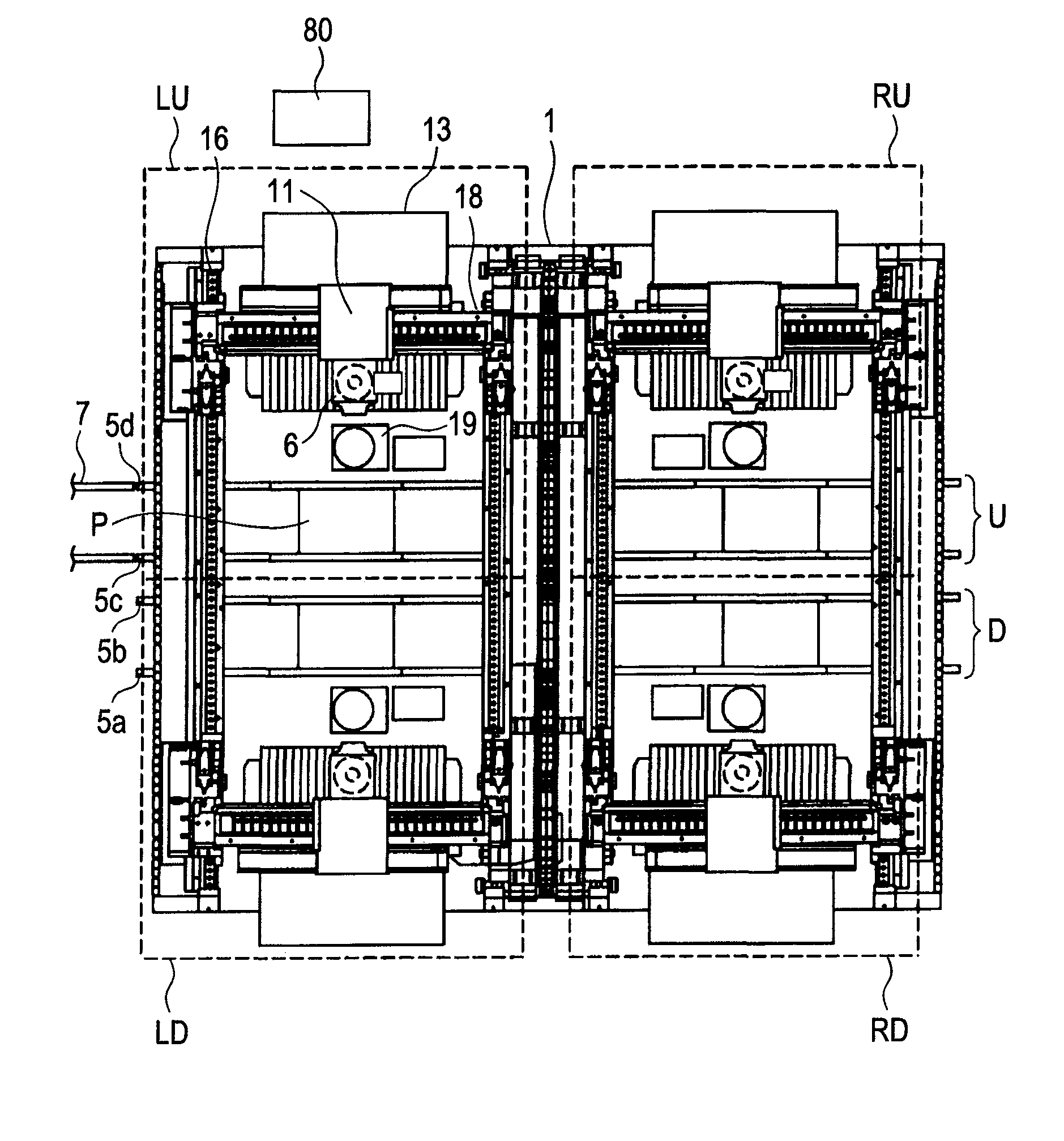
[0028]Embodiments of the electronic component mounting apparatus will be described in further detail with reference to the accompanying drawings. FIG. 1 is a plan view of an electronic component mounting apparatus 1 according to an embodiment of the invention. The electronic component mounting apparatus 1 (or shortly a main unit 1 as needed) includes four blocks, two upper and lower blocks LU and LD at the left side and two upper and lower blocks RU and RD at the right side, and a controller 80. Basically, reference numerals are provided for the LU block only. Each block is provided with a component supply area 13, a mounting head 6, a mounting head unit 11, and a component monitoring camera 19. The component supply area 13 is provided with many tape feeders. The mounting head unit 11 moves the mounting head 6. The component monitoring camera 19 captures how the mounting head absorbs and holds an electronic component. The mounting head unit 11 horizontally moves along a horizontal r...


PUM

PropertyMeasurementUnit
sizeaaaaaaaaaa
shapeaaaaaaaaaa
timeaaaaaaaaaa

Abstract

There is a need for providing an electronic component mounting apparatus, a component supply apparatus, and an electronic component mounting method capable of reducing inadvertent insertion of component supply tape and ensuring high reliability or capable of reducing wrong insertion of component supply tape, supplying new electronic component tape, and ensuring a high operation rate. Supply tape is inserted into an insertion entry of a component supply apparatus. An electronic component mounted on the supply tape is absorbed and is mounted on a printed board. Information about the electronic component mounted on the supply tape is read. Based on the read information, the component supply apparatus for inserting the supply tape is selected. The insertion entry is opened while it is closed when no supply tape is mounted.

Description

BACKGROUND OF THE INVENTION[0001]1. Field of the Invention[0002]The present invention relates to an electronic component mounting apparatus, a component supply apparatus, and an electronic component mounting method. More particularly, the invention relates to an electronic component mounting apparatus, a component supply apparatus, and an electronic component mounting method with high reliability capable of preventing wrong insertion operations of supply tape.[0003]2. Description of Related Art[0004]There is an increasing demand for improving the operation rate of an electronic component mounting apparatus for manufacturing circuit boards by mounting electronic components on printed boards. For this purpose, it is important to not only finish supplying or rearranging electronic components in a short period of time but also correctly and reliably mount a component supply cart with proper electronic components.[0005]JP-A No. 226975 / 2008 discloses a conventional technology. According t...

Claims


Application Information

Patent Timeline
Patent Type & Authority Applications(United States)
IPC IPC(8): H05K3/30B23P19/00
CPCH05K13/0417Y10T29/53174Y10T29/53183Y10T29/4913Y10T29/53178H05K13/0419
Inventor OYAMA, KAZUYOSHIYANAGIDA, TSUTOMUUSUI, YOSHINAO
Owner YAMAHA MOTOR CO LTD
Why Eureka
Try Eureka