Printer having detachably mounted platen roller

Inactive Publication Date: 2011-03-31
ALPS ALPINE CO LTD
View PDF6 Cites 14 Cited by
  • Summary
  • Abstract
  • Description
  • Claims
  • Application Information

AI Technical Summary

Benefits of technology

[0025]The various embodiments have the effect that the plate spring is arranged in a narrow space, furthermore the length for deformation can be secured sufficiently so that the head un

Problems solved by technology

The printer described in Japanese Unexamined Patent Application Publication No. 2007-118247 is unstable in the regulation of the shaft because rotated hook elements face an opening of the groove section after the shaft of the platen roller is mounted in the groove section of the frame so as to regulate the deviation of the shaft from the groove section of the shaft.
Because there is a limit of

Method used


Image

  • Printer having detachably mounted platen roller
  • Printer having detachably mounted platen roller
  • Printer having detachably mounted platen roller

Examples


Embodiment Construction

[0030]The following description is intended to convey a thorough understanding of the embodiments described by providing a number of specific embodiments and details involving printers having detachably mounted platen rollers. It should be appreciated, however, that the present invention is not limited to these specific embodiments and details, which are exemplary only. It is further understood that one possessing ordinary skill in the art, in light of known systems and methods, would appreciate the use of the invention for its intended purposes and benefits in any number of alternative embodiments, depending on specific design and other needs.

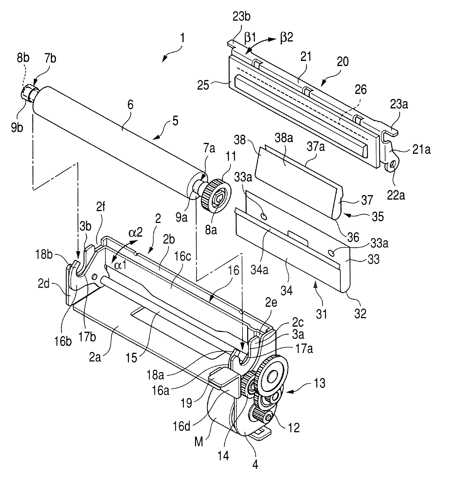
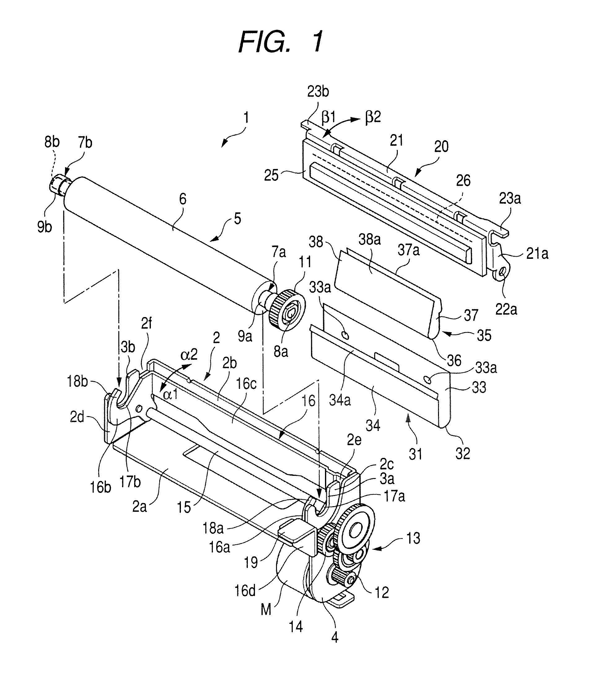
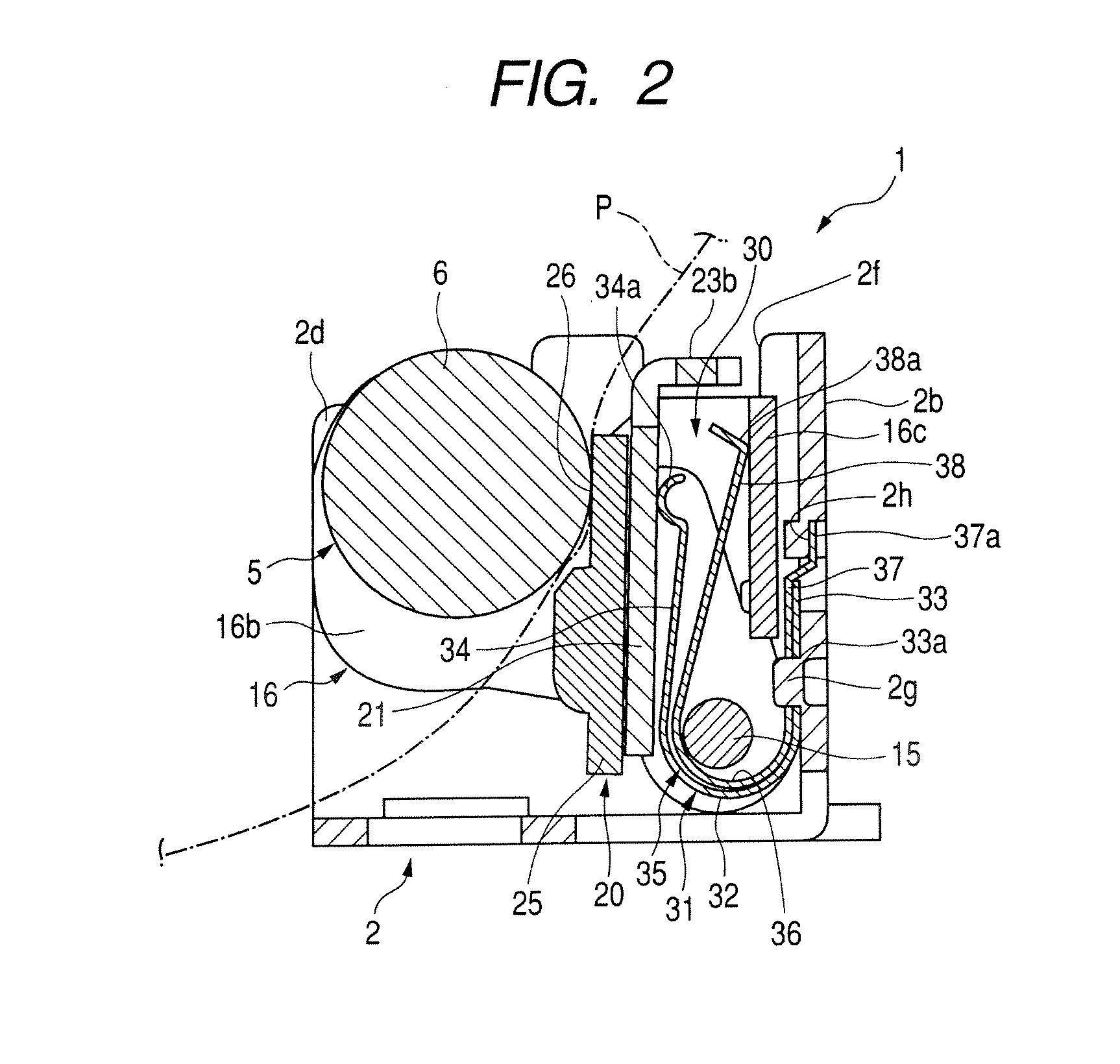
[0031]A printer 1 an exemplary embodiment shown in FIG. 1 and FIG. 2 may be used in the receipt issuing section or the like of a cash register or other apparatus.

[0032]The printer 1 may have a frame 2. The frame 2 may be formed by bending a sheet metal material, for example. The frame 2 may have a bottom plate section 2a and a rear plate secti...


PUM


Abstract

A printer includes a platen roller that is detachably supported on a support section that is formed in a frame, and a head unit that is supported on the frame and can be moved in a direction in which the head unit is brought into pressure-contact with the platen roller, The printer also includes a regulating member that is movably supported on the frame, and the regulating member has a regulating section that regulates a shaft of the platen roller to deviate from the support section and a pressing section that is arranged on the opposite side to the regulating section, with the head unit interposed therebetween. A first plate spring that presses the head unit against the platen roller and a second plate spring that presses the pressing section so as to bias the regulating member in a direction in which the regulating section can regulate the shaft are provided in an area on the opposite to the platen roller, with the head unit interposed therebetween.

Description

CROSS REFERENCE TO RELATED APPLICATION[0001]The present invention contains subject matter related to and claims the benefit of Japanese Patent Application JP 2009-227300 filed in the Japanese Patent Office on Sep. 30, 2009, the entire contents of which is incorporated herein by reference.BACKGROUND OF THE DISCLOSURE[0002]1. Technical Field[0003]The present invention relates a printer that detachably mounts a platen roller when a paper for printing is set or the like.[0004]2. Related Art[0005]A compact printer is used in the receipt issuing section or the like of a cash register or various other like apparatus. As described in Japanese Unexamined Patent Application Publication No. 2007-118247 and Japanese Unexamined Patent Application Publication No. 2008-179079, this kind of compact printer is a line printer that includes a thermal head and has a head unit and a platen roller that pushes the head unit. Since the platen roller is detachably mounted, the platen roller is detached and ...

Claims


Application Information

Patent Timeline
IPC IPC(8): B41F1/38
CPCB41J15/042B41J11/04
Inventor KAMATA, SHIGEYUKI
Owner ALPS ALPINE CO LTD
Why Eureka
Try Eureka