Shrouded vertical axis dual-turbine generator

a generator and vertical axis technology, applied in the direction of electric generator control, renewable energy generation, greenhouse gas reduction, etc., can solve the problems of increasing the speed of the turbine, adding vacuum, etc., to increase the speed of the blades, prevent flying debris from damaging the rotor, and increase the low pressure zone

Inactive Publication Date: 2013-04-30
BAILEY LAURA J +1
View PDF22 Cites 19 Cited by
  • Summary
  • Abstract
  • Description
  • Claims
  • Application Information

AI Technical Summary

Benefits of technology

[0010]The shrouded vertical axis dual-turbine generator is a generator of electricity or power to be used in air flow or submerged in a water flow. The shrouded vertical axis turbine is composed of a variable height structure in the shape of a vertical, symmetrical foil shaped as two joined airplane wings. The vertical axis turbines are set into the two specially-shaped cambers at both sides of the foil. The shape of the foil, as two joined airplane wings, takes advantage of Bernoulli's principle, to increase the speed of the air or water current that flows toward the turbines. The trailing end of the foil creates a slip stream to eliminate energy-robbing turbulence which would adversely affect the efficiency of the turbines, and also reducing turbulence between generators, when multiple generators are placed together, to increase the efficient use of areas available for energy production.
[0011]The two fixed, symmetric cambers, are designed in such a way that the space between the foil and the turbine is narrower toward the front and wider toward the rear of the camber. The wider space to the rear creates a high pressure area and the narrower space toward the front creates a low pressure area. This difference in pressure of these two areas generates an additional vacuum that increases the speed of the turbines.
[0013]The space between the turbine rotors and the shutters is a low pressure zone which contributes to increase the speed of the blades around into the current. In high speed currents, the shutters can slide back to isolate the turbines from the current.
[0014]The design of the turbines takes advantage of the increased low pressure zone, still allowing the turbines to turn when other turbines would be shut down. The shutters can also slide backward to shelter the blades of the turbines from the wind or water current for a controlled shut down or to shelter them from unusually strong winds or current during storms, thus preventing flying debris from damaging the rotors.
[0015]Because each turbine is made of multiple blades that are staggered in a spiral pattern, pressure lock at start up is eliminated while the back pressure at cruising speed is reduced. The space between the tips of the blades reduces drag at full speed by reducing back pressure.
[0016]The novel design of the shrouded vertical axis dual-turbine generator is aimed to the building a compact generator that can be utilized in situations where multiple generators are needed in the same close area, achieving a reduced turbulence between generators, in order to better utilize areas available for energy production and make a generator that works in very low to very high current speeds using either wind or water.

Problems solved by technology

This difference in pressure of these two areas generates an additional vacuum that increases the speed of the turbines.
As one of the major problem affecting wind turbines being the uncontrolled speed of the rotors causing the burning and destruction of the ball-bearings of the turning axe's, the speed of the turbines is controlled by shutters that slide in tracks.

Method used


Image

  • Shrouded vertical axis dual-turbine generator
  • Shrouded vertical axis dual-turbine generator
  • Shrouded vertical axis dual-turbine generator

Examples


Embodiment Construction

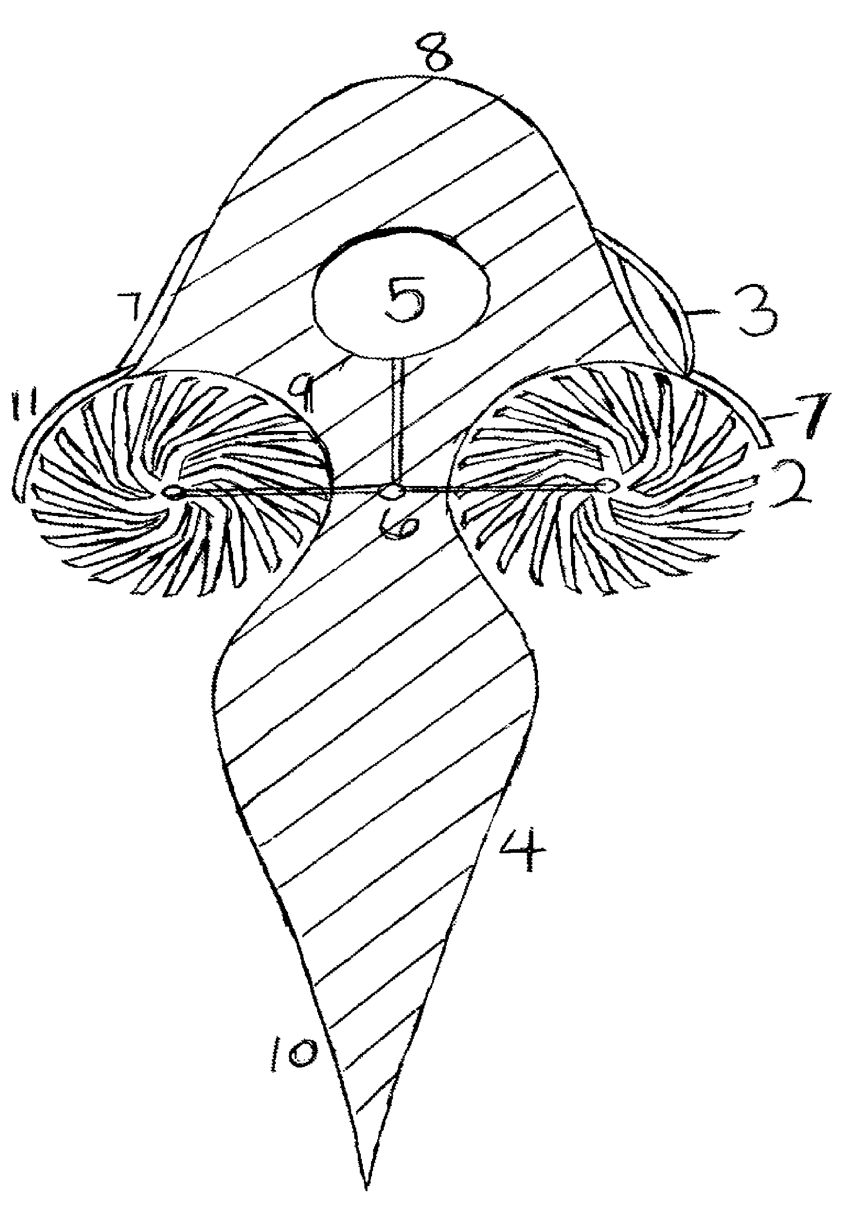
[0021]FIG. 1 illustrates a single blade 1 of the turbine's rotor with six lobes, although the number of lobes can vary between three and six to achieve optimum efficiency. The second half of each lobe is at a different angle than the first half of the lobe 12, while the tip of each lobe is at a steeper angle than the second half of the lobe 12.

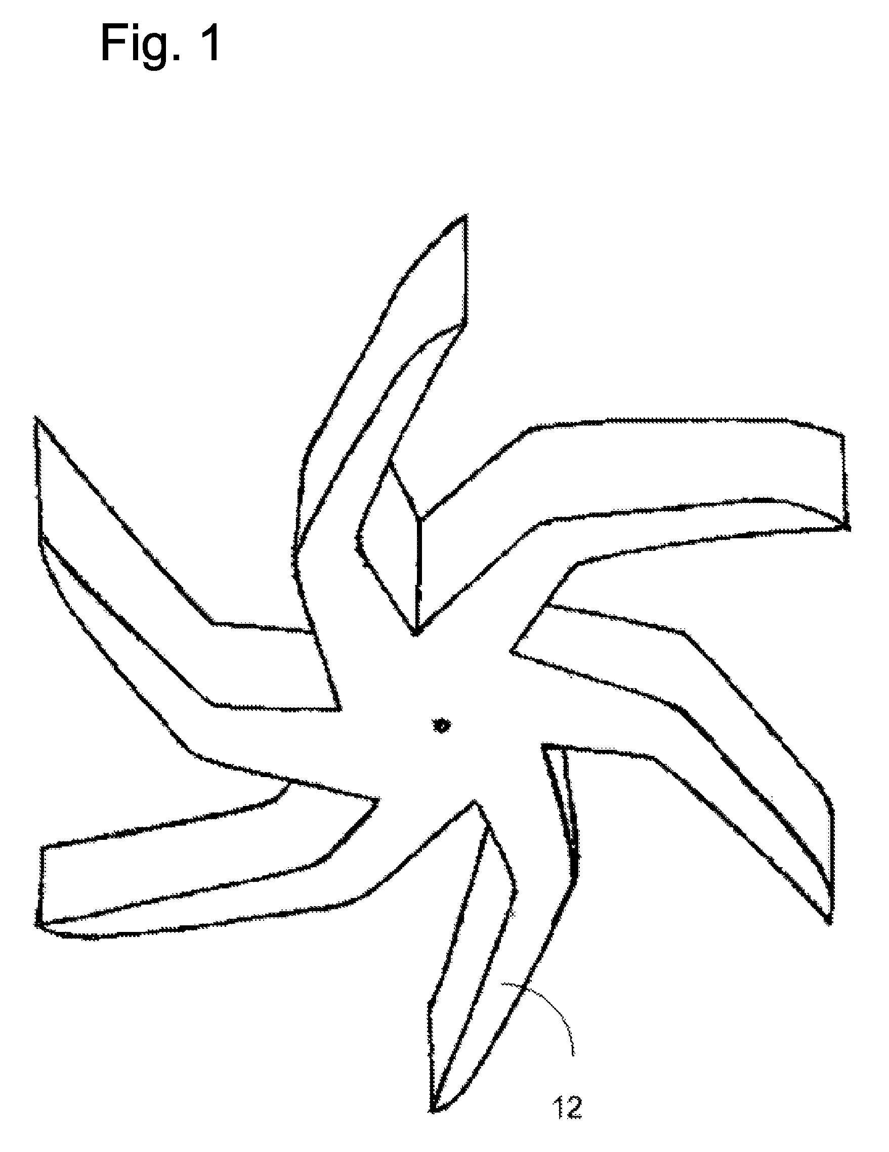
[0022]The turbines of the shrouded vertical axis dual-turbine generators are of a modular design, comprised of multiple blades. The number of blades can be staggered in a spiral pattern to form a tower, according to FIG. 2, to facilitate the start up of the turbines 2 reducing the back pressure at cruising speed. The staggering of the blades 1 creates a space between the tips of the blades reducing the amount of energy needed for starting up the rotation of the turbine 2 and reducing drag at full speed by reducing back pressure.

[0023]Each blade comprises a plurality of lobes, where each second part of a lobe is at a different angle than the fi...


PUM


Abstract

The shrouded vertical axis dual-turbine generator is a system comprising a structure in the shape of a double airplane wings symmetrical foil, having a vertical axis turbine set into each camber at each side of the foil. The aerodynamic shape of the leading edge of the foil increases the speed of the water or air current incoming toward the generator. The trailing edge of the foil creates a slip stream which reduces turbulence. Movable shutters on each side of the foil structure control the amount of current to the turbines and sheltering them from storm and debris. The turbines have a modular design and can be made of a stacked number of blades.

Description

RELATED APPLICATIONS[0001]This application claims benefit of Provisional application No. 60 / 904,411 filed on Mar. 2, 2007.BACKGROUND OF THE INVENTION[0002]1. Field of the Invention[0003]This invention relates to wind turbines, and in particular wind turbines having a vertical axis and a variable number of stackable blades.[0004]2. Brief Description of the Prior Art[0005]Alternative energy sources are greatly needed as the world reaches peak oil. Coal is still plentiful, and would last possibly for centuries, but the pollution and environmental destruction caused by the coal industry is unsustainable. Wind energy is one great source of renewable energy. The majority of wind energy is produced with extremely large horizontal axis turbines. One of the problems with these turbines is the turbulence created by these large blades. As a result of this turbulence, these turbines must be spaced three to ten times their diameter apart (side to side) and in rows five to ten times their diamete...

Claims


Application Information

Patent Timeline
Patent Type & Authority Patents(United States)
IPC IPC(8): F03B13/00H02P9/04F03D9/00F03B13/10
CPCF03B1/02F03B17/063F03D3/0454F05B2240/40Y02E10/223Y02E10/28Y02E10/74F03D3/02Y02E10/20
Inventor BAILEY, LAURA J.BAILEY, JOHN T.
Owner BAILEY LAURA J
Why Eureka
Try Eureka