Cooling system for construction machine

a construction machine and cooling system technology, applied in the field of construction machines, can solve the problems of difficulty in maintaining the cooling performance of each heat exchanger, and achieve the effects of improving assembly operation efficiency, easy movement, and improving maintenance operation efficiency

Active Publication Date: 2013-08-13
NIHON KENKI CO LTD
View PDF16 Cites 20 Cited by
  • Summary
  • Abstract
  • Description
  • Claims
  • Application Information

AI Technical Summary

Benefits of technology

[0011]In consequence, since the respective heat exchangers can be arranged such that the heat release amount sequentially increases from the upstream side toward the downstream side in the flow direction of the cooling air, each heat exchanger can efficiently release the heat of the fluid to be cooled. In general, since each of the condenser and the fuel cooler has a thickness dimension smaller than that of the intercooler, when the fuel cooler is arranged at the front surface side of the condenser, two heat exchangers can be substantially accommodated within a range of the thickness dimension of the intercooler.
[0012]As a result, the radiator, the oil cooler, the intercooler, the condenser and the fuel cooler can be arranged in a compact size and these heat exchangers can be arranged in a narrow space on the vehicle body. Besides, since the respective heat exchangers are arranged in consideration of the heat release amount of each, the cooling performance of each heat exchanger can be maintained.
[0016]With this arrangement, when the outside air is sucked in by the cooling fan, the dust protective net can trap dusts, insects and the like in the outside air. Therefore, one dust protective net can restrict dusts and the like to be accumulated in the plural heat exchangers, reducing the number of times of cleaning these heat exchangers. The dust protective net provided on the most upstream position can easily clean the trapped dusts, insects and the like.
[0018]With this arrangement, the air hose at the inlet side and the air hose at the outlet side can be easily mounted and removed to and from the engine and the intercooler, improving an assembly operational efficiency, a maintenance operational efficiency and the like.
[0019]Since the air hose at the inlet side and the air hose at the outlet side connect the engine and the intercooler to ride over the top surface of the radiator and the oil cooler, each air hose can be easily moved in a state where each air hose is removed from the intercooler. Therefore, the radiator and the oil cooler can be pulled upwards independently for removal, easily performing the cleaning operation, the repair operation and the like of the radiator and the oil cooler.
[0021]With this arrangement, since the support body of the frame structure can guide the cooling air flown in from the outside toward the cooling fan, the fluid to be cooled by the radiator, the oil cooler, the intercooler, the condenser and the fuel cooler can be efficiently cooled.

Problems solved by technology

Therefore, in a case of further disposing the fuel cooler in this narrow space, there occurs a problem with difficulty of maintaining cooling performance of each heat exchanger.

Method used


Image

  • Cooling system for construction machine
  • Cooling system for construction machine
  • Cooling system for construction machine

Examples


Embodiment Construction

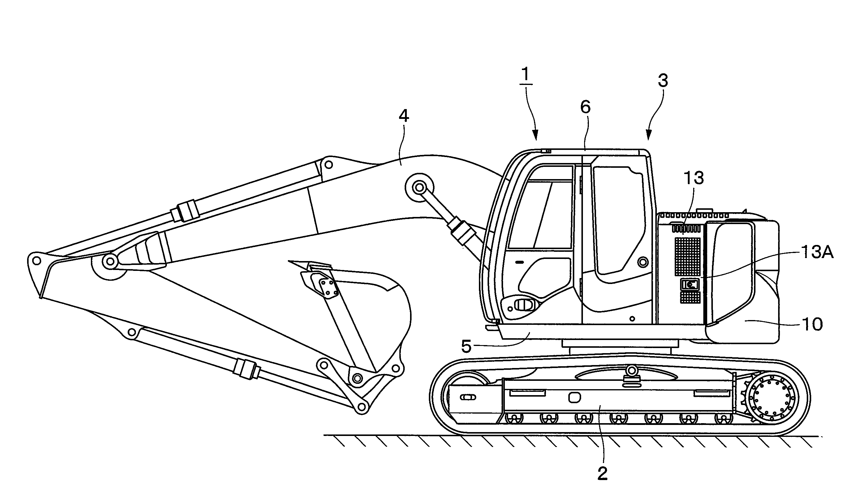
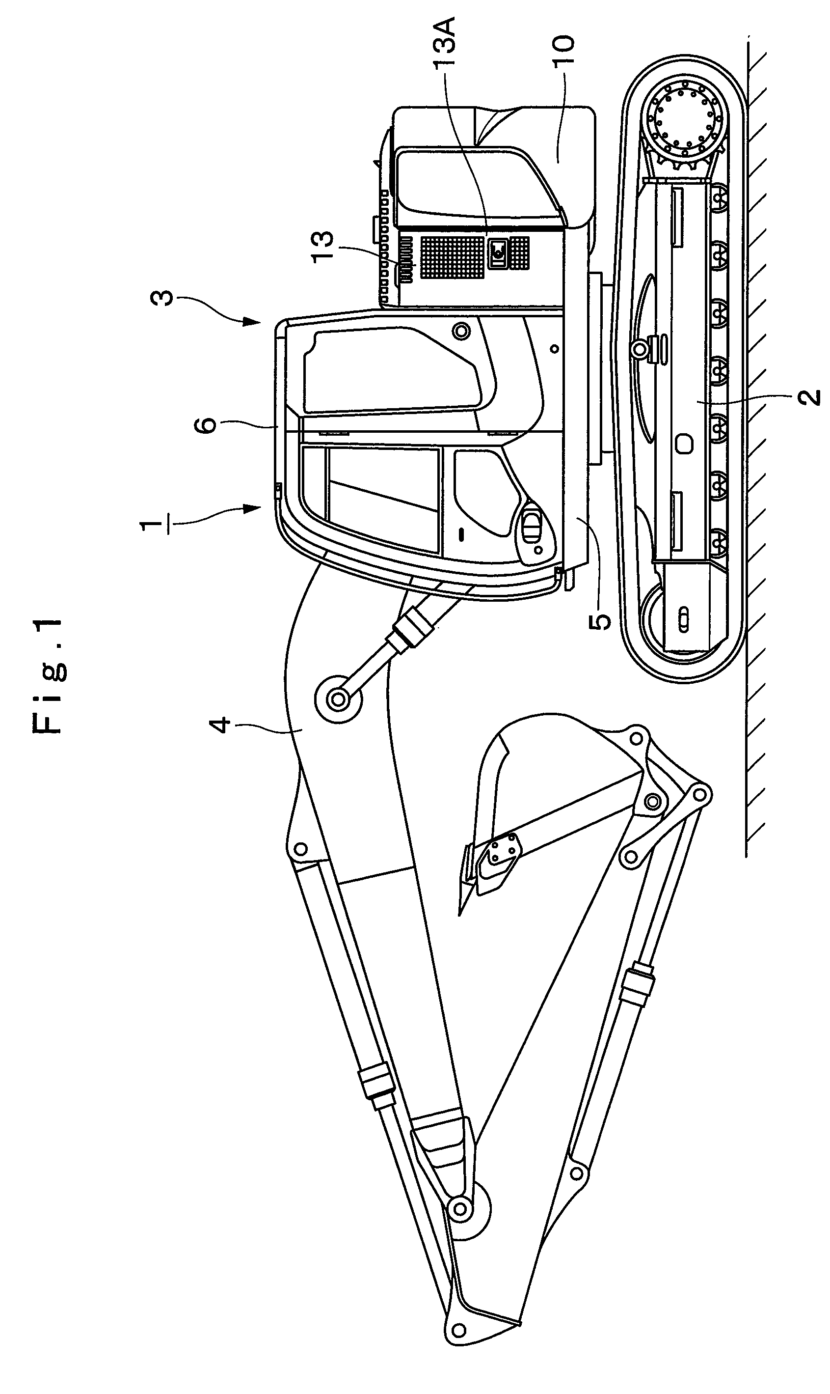
[0032]Hereinafter, as a representative example of a construction machine in an embodiment according to the present invention, a detailed description will be given of a hydraulic excavator equipped with a radiator, an oil cooler, an intercooler, a condenser of an air conditioner and a fuel cooler with reference to FIG. 1 to FIG. 9.

[0033]In FIG. 1, denoted at 1 is a crawler type hydraulic excavator as a construction machine. The hydraulic excavator 1 is largely constituted by an automotive lower traveling structure 2, an upper revolving structure 3 swingably mounted on the lower traveling structure 2 and a working mechanism 4 liftably provided at a front side of the upper revolving structure 3 in front and rear directions to perform a ground excavating operation of earth and sand. The lower traveling structure 2 and the upper revolving structure 3 constitute a vehicle body in the present invention. Here, the hydraulic excavator 1 is constituted such that the upper revolving structure ...


PUM


Abstract

A radiator and an oil cooler are arranged at a front surface side of a cooling fan in parallel with each other in a flow direction of the cooling air, an intercooler and a condenser are arranged in parallel at a front surface side of the radiator and oil cooler, and a fuel cooler is arranged at a front surface side of the condenser. By arranging respective heat exchangers such that the heat release amount thereof sequentially increases from the upstream side toward the downstream side in the flow direction of the cooling air, each heat exchanger can efficiently release the heat of the fluid to be cooled. By arranging the fuel cooler at the front surface side of the condenser, two heat exchangers of the condenser and the fuel cooler can be accommodated within a range of the thickness dimension of the intercooler.

Description

TECHNICAL FIELD[0001]The present invention relates to a construction machine such as a hydraulic excavator and the like, and particularly to a construction machine equipped with a radiator, an oil cooler, an intercooler, a condenser of an air conditioner and a fuel cooler.BACKGROUND ART[0002]In general, a hydraulic excavator as a representative example of a construction machine is largely constituted by an automotive lower traveling structure, an upper revolving structure swingably mounted on the lower traveling structure, and a working mechanism liftably mounted at a front side of the upper revolving structure.[0003]The upper revolving structure is largely constituted by a revolving frame as a support structural body, a cab located at a front side of the revolving frame for an operator to get on, an engine mounted at a rear side of the revolving frame, a hydraulic pump which is driven by the engine to pressurize operating oil for supply, a cooling fan which is rotated by the engine...

Claims


Application Information

Patent Timeline
Patent Type & Authority Patents(United States)
IPC IPC(8): F01P1/06
CPCB60K11/04E02F9/00E02F9/0866F01P3/18F02B29/0431F02B29/0456F02B29/0475F02M31/20B60Y2200/412F01P2003/187F02M35/10131F02M35/10347Y02T10/146Y02T10/126Y02T10/12
Inventor HIRASAWA, SHIGERUMATSUSHITA, MAKOTOMAMADA, TOMONORI
Owner NIHON KENKI CO LTD
Why Eureka
Try Eureka