Compression Assembly and Method for Actuating Downhole Packing Elements

a compression assembly and packing element technology, applied in the field of downhole tools, can solve the problem of limited use of through tubing bridge plugs in wells

Active Publication Date: 2011-03-31
HALLIBURTON ENERGY SERVICES INC
View PDF73 Cites 50 Cited by
  • Summary
  • Abstract
  • Description
  • Claims
  • Application Information

AI Technical Summary

Benefits of technology

In a eleventh aspect, the present invention is directed to a method for actuating packing elements of a bridge plug in a casing string of a wellbore. The method includes conveying the bridge plug through a tubing string in the wellbore to a target location in the casing string, applying a compressive force between a pair of compression assemblies of the bridge plug, operating a support assembly of each compression assembly from a running configuration in which link arm assemblies are substantially longitudinally oriented to an operating configuration in which short arms are pivoted relative to long arms of the link arm assemblies to form a support platform, operating an anti extrusion assembly of each compression assembly from a running configuration in which petals are substantially perpendicular to a base member and nested relative to one another to an operating configuration in which the petals are radially outwardly disposed substantially filling gaps between the short arms and actuating the packing elements into sealing contact with the casing string.

Problems solved by technology

It has been found, however, that the use of through tubing bridge plugs is limited to wells that require only a relatively small expansion ratio between the sealing configuration of the through tubing bridge plug and the running configuration of the through tubing bridge plug.

Method used


Image

  • Compression Assembly and Method for Actuating Downhole Packing Elements
  • Compression Assembly and Method for Actuating Downhole Packing Elements
  • Compression Assembly and Method for Actuating Downhole Packing Elements

Examples


Embodiment Construction

While the making and using of various embodiments of the present invention are discussed in detail below, it should be appreciated that the present invention provides many applicable inventive concepts which can be embodied in a wide variety of specific contexts. The specific embodiments discussed herein are merely illustrative of specific ways to make and use the invention, and do not delimit the scope of the present invention.

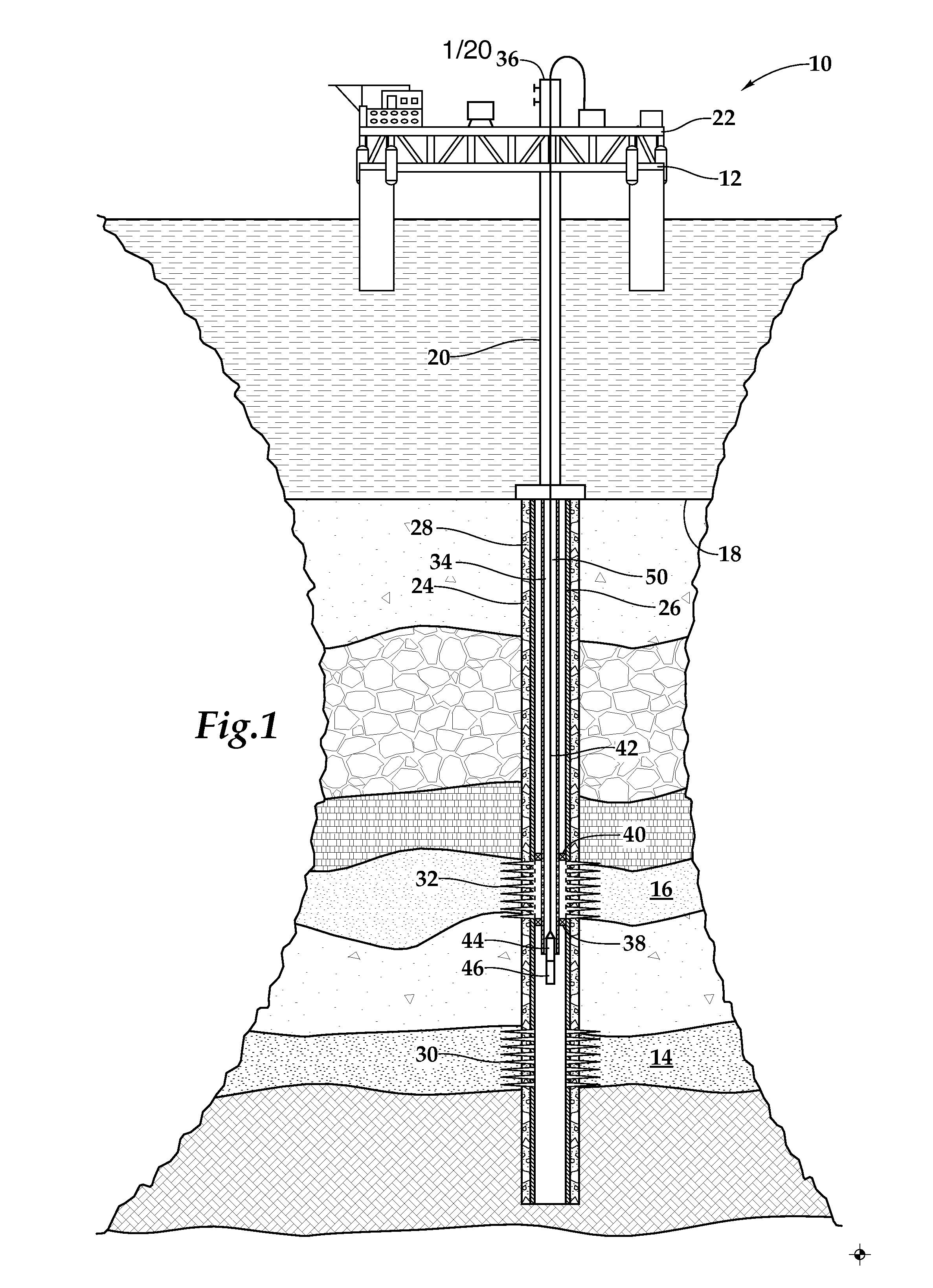
Referring initially to FIG. 1, a through tubing bridge plug of the present invention is being installed from an offshore oil and gas platform that is schematically illustrated and generally designated 10. A semi-submersible platform 12 is centered over submerged oil and gas formations 14, 16 located below sea floor 18. A subsea conductor 20 extends from deck 22 of platform 12 to sea floor 18. A wellbore 24 extends from sea floor 18 and traverse formations 14, 16. Wellbore 24 includes a casing 26 that is supported therein by cement 28. Casing 26 has two sets o...


PUM


Abstract

A compression assembly (500) for actuating packing elements of a through tubing bridge plug in a casing string of a wellbore. The compression assembly (500) includes a support assembly (502) and an anti extrusion assembly (504). The support assembly (502) has a running configuration in which link arm assemblies are substantially longitudinally oriented and an operating configuration in which short arms (514) are pivoted relative to long arms (520) of link arm assemblies such that the short arms (514) form a support platform. The anti extrusion assembly (504) is operably associated with the support assembly (502). The anti extrusion assembly (504) has a running configuration in which petals (536) are substantially perpendicular to a base member (534) and nested relative to one another and an operating configuration in which the petals (536) are radially outwardly disposed substantially filling gaps between the short arms (514).

Description

TECHNICAL FIELD OF THE INVENTIONThis invention relates, in general, to equipment utilized in conjunction with operations performed in a subterranean well and, in particular, to a downhole tool that is positioned in a subterranean well to isolate a lower portion of the well from an upper portion of the well.BACKGROUND OF THE INVENTIONBridge plugs are well tools that are typically lowered into a cased oil or gas well and set at a desired location inside the casing to isolate pressure between two zones in the well. Retrievable bridge plugs are used during drilling and workover operations to provide a temporary separation of zones. Permanent bridge plugs are used when it is desired to permanently close off the well above a lower zone or formation when, for example, that lower zone has become non-productive but one or more upper zones remain productive. In such cases, a through tubing bridge plug may be installed without the need for pulling the tubing or killing the well. Such through t...

Claims


Application Information

Patent Timeline
Patent Type & Authority Applications(United States)
IPC IPC(8): E21B33/12
CPCE21B23/01E21B23/06E21B33/1208E21B33/136E21B33/128E21B33/134E21B33/1216
Inventor CLEMENS, JACK GAMMILLLUDWIG, WESLEY NEILRODGERS, JOHN PATRICKEATON, EDWIN A.SERRA, MARCO
Owner HALLIBURTON ENERGY SERVICES INC
Why Eureka
Try Eureka