Cooling structure of motor

a technology of cooling structure and motor, which is applied in the direction of dynamo-electric machines, magnetic circuit rotating parts, magnetic circuit shape/form/construction, etc., can solve the problem of limited and achieve the effect of further efficient removal of heat evolved in the rotor

Inactive Publication Date: 2011-03-31
NTN CORP
View PDF5 Cites 19 Cited by
  • Summary
  • Abstract
  • Description
  • Claims
  • Application Information

AI Technical Summary

Benefits of technology

[0020]By providing the oil guide ring, the cooling oil flowing from the end portion of the cooling space towards the outer diametric side can be guided so as to reach the rotor spindle or the rotor core and, therefore, the rotor spindle or the rotor core can be cooled by this cooling oil. Therefore, as compared with the case, in which the cooling is effected with the cooling oil from only the inner peripheral surface of the rotor spindle, the heat evolved in the rotor can be removed further efficiently.
[0021]The cooling structure of any of the types referred to above can be adopted in a variety of motors. The motor, in which the cooling structure of the present invention is adopted, is excellent in that the interior of such motor is cooled.

Problems solved by technology

However, removal of the heat evolved in the rotor is limited because no cooling oil so scattered impinge upon the rotor.

Method used


Image

  • Cooling structure of motor
  • Cooling structure of motor
  • Cooling structure of motor

Examples


Embodiment Construction

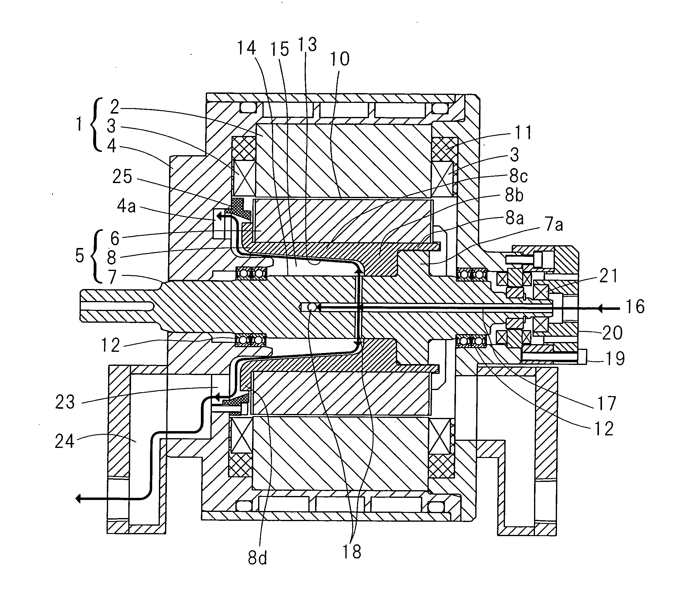
[0026]A first embodiment of the present invention will be described in detail with particular reference to FIG. 1. The motor, to which this cooling structure is applied, is made up of a stator 1 and a rotor 5 and is a motor of a radial gap type, in which a radially spaced gap portion 10 is provided intermediate between a stator core 2 of the stator 1 and a rotor core 6 of the rotor 5.

[0027]The stator 1 includes the stator core 2 referred to above and having an annular shape, a stator coil 3 arranged on opposite axial sides of the stator core 2, and a stator housing 4 accommodating the stator core 2 and the stator coil 3. The stator core 2 is specifically of a type, in which a stator coil is wound around each of a plurality of cores arranged in an annular configuration, and is fixed to an inner peripheral surface of the stator housing 4. A space delimited by and among the stator core 2 and the stator coil 3 and the stator housing 4 is molded by a molding material 11.

[0028]The rotor 5...


PUM


Abstract

An internal cooling structure for a motor, which is effective to remove the heat in the rotor to achieve high cooling effect is provided. The motor includes a stator having a stator coil and a stator core, and a rotor positioned on an inner side of the stator core. The rotor includes a tubular rotor spindle on a rotor drive shaft, and the rotor core is fitted to the rotor spindle. A cooling space is defined between the rotor drive shaft and the rotor spindle. An inner peripheral surface of the rotor spindle confronting the cooling space has tapered shape having large diameter at an end portion. An oil feed passage for a cooling oil is defined inside the rotor drive shaft, and a cooling oil discharge port of such oil feed passage is formed in the rotor drive shaft confronting the cooling space.

Description

CROSS REFERENCE TO THE RELATED APPLICATION[0001]This application is based on and claims Convention priority to Japanese patent application No. 2008-144134, filed Jun. 2, 2008, the entire disclosure of which is herein incorporated by reference as a part of this application.BACKGROUND OF THE INVENTION[0002]1. Field of the Invention[0003]The present invention relates to a cooling structure employed within a motor of a kind, in which a rotor is disposed on an inner side of a stator core.[0004]2. Description of the Related Art[0005]For an internal cooling system employed in a motor of a kind including a stator having a stator coil and a stator core arranged or formed in an annular shape, and a rotor positioned on an inner peripheral side of the stator core for rotation relative to the stator, the Patent Document 1 listed below, for example, discloses the use of a hollow shaft for a rotor drive shaft, the hollow of the rotor drive shaft being communicated with an outer peripheral side thr...

Claims


Application Information

Patent Timeline
Patent Type & Authority Applications(United States)
IPC IPC(8): H02K9/19
CPCH02K9/19H02K1/32H02K9/197
Inventor OKADA, KOICHIMAKINO, YUSUKESUGIURA, KEN
Owner NTN CORP
Why Eureka
Try Eureka