Bioreactor with condenser

a technology of condenser and bioreactor, which is applied in the field of bioreactor, can solve the problems of affecting the efficiency of the bioreactor, the inability to transfer to the bioreactor, and the relative long length of the gas dissipation duct, so as to avoid the blockage of the hydrophobic filter by condensed liquid

Active Publication Date: 2011-03-31
SARTORIUS STEDIM BIOTECH GMBH
View PDF15 Cites 46 Cited by
  • Summary
  • Abstract
  • Description
  • Claims
  • Application Information

AI Technical Summary

Benefits of technology

[0022]According to a further preferred embodiment of the invention, the sterile filter has on its circumference heating which makes it possible to control the temperature of the exhaust air, with the result that blockage of the hydrophobic filte

Problems solved by technology

The disadvantage, here, is that, in the case of a largely laminar flow, a relative long gas dissipation duct is required in order to cool the entire exhaust air stream sufficiently.
Particularly when a bioreactor is used as a disposable reactor with a condenser, it is diff

Method used


Image

  • Bioreactor with condenser
  • Bioreactor with condenser
  • Bioreactor with condenser

Examples


Embodiment Construction

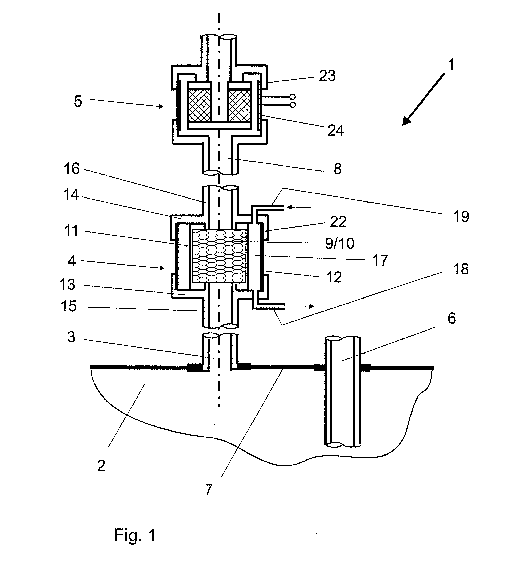
[0035]A bioreactor 1 is composed essentially of a vessel 2, of a gas dissipation duct 3, of a condenser 4, of a sterile filter 5 and of a gas supply duct 6.

[0036]The vessel 2 is designed as a bag made from plastic with a flexible wall 7 and has, inter alia, in addition to the gas dissipation duct 3, the gas supply duct 6.

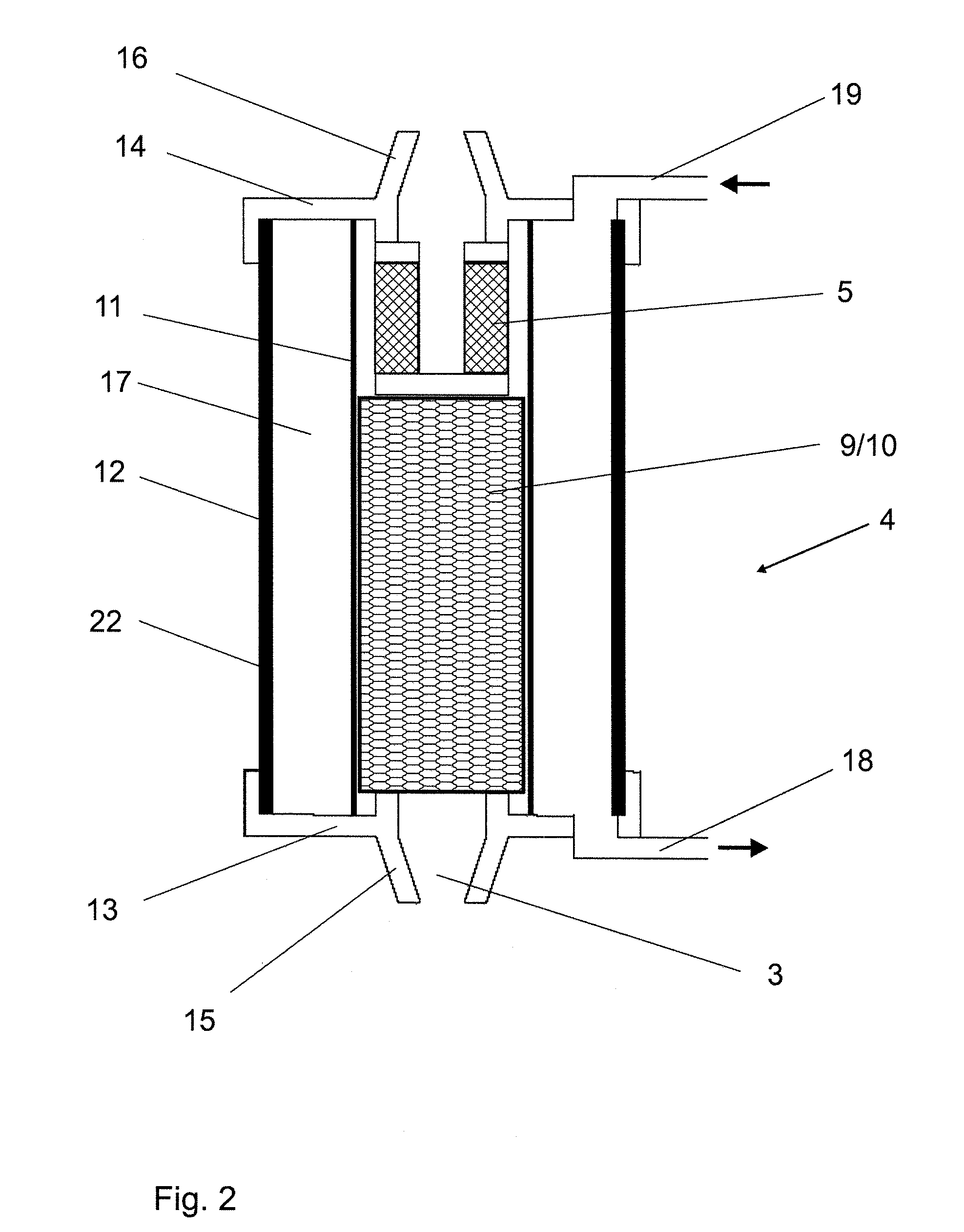
[0037]The orifice 8 of the gas dissipation duct 3 is connected to the hydrophobic sterile filter 5. The condenser 4 is arranged in the gas dissipation duct 3 between the vessel 2 and sterile filter 5.

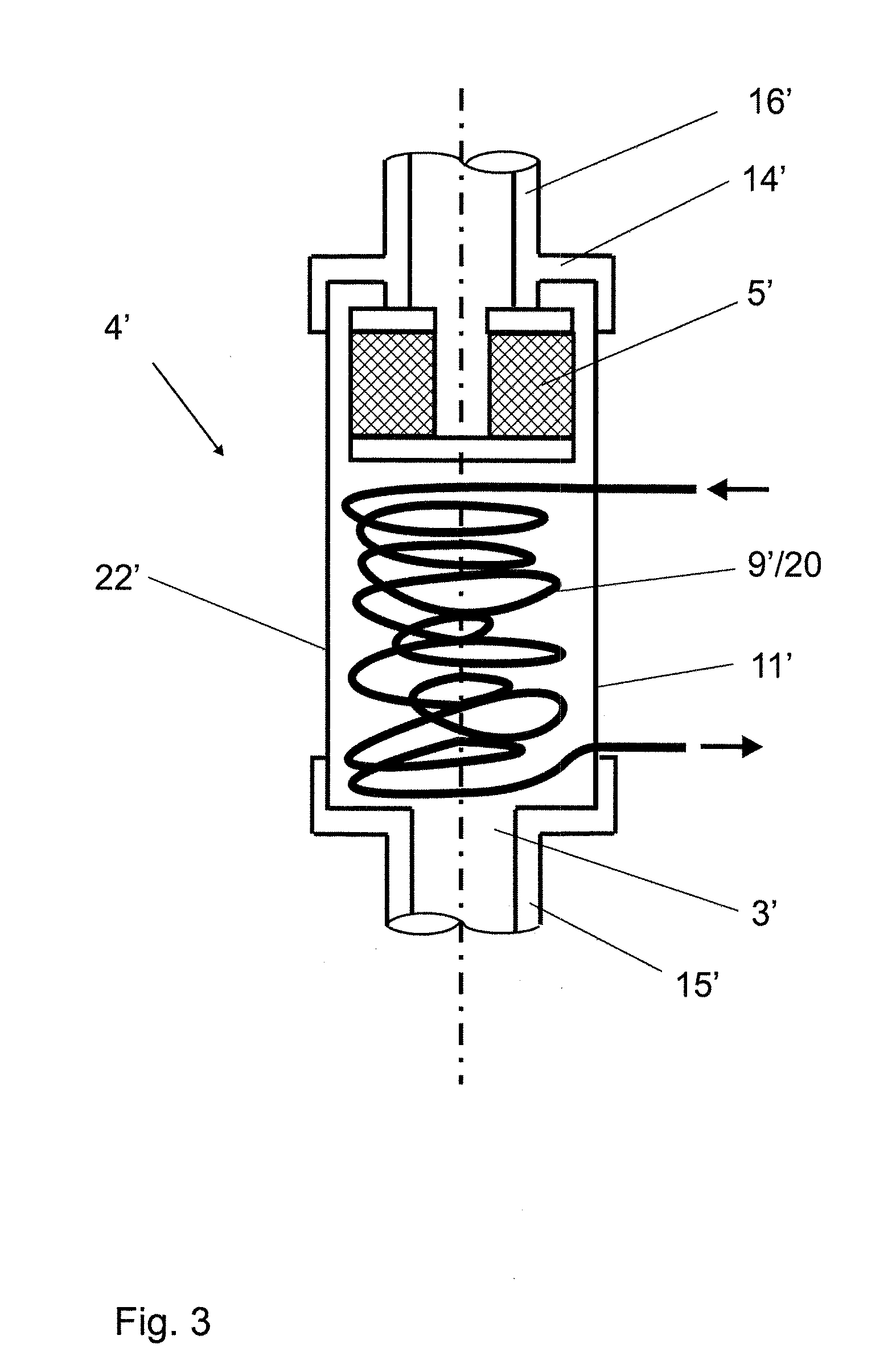
[0038]Turbulence generation means 9 for generating a turbulent flow are arranged in the gas dissipation duct 3 in the region of the condenser 4.

[0039]According to the exemplary embodiment of FIG. 1 and FIG. 2, the turbulence generation means 9 are designed as a packing 10 inserted into the gas dissipation duct 3 and composed of a nonwoven material or of tubular segments made from glass, ceramic, plastic or metal, and the wall 11 surrounding the gas dissipation duct 3 is...


PUM


Abstract

Bioreactor with a vessel having at least one gas dissipation duct for gas discharge, the orifice of the gas dissipation duct being connected to a hydrophobic sterile filter and to a condenser arranged between them and having condensation surfaces, a turbulence generator for generating a turbulent flow is arranged in the gas dissipation duct in the region of the condenser.

Description

BACKGROUND OF THE INVENTION[0001]1. Field of the Invention[0002]The invention relates to a bioreactor with a vessel having at least one gas dissipation duct for gas discharge, the orifice of the gas dissipation duct being connected to a sterile filter and to a condenser arranged between them and having condensation surfaces.The invention relates, furthermore, to a condenser for a bioreactor.[0003]2. Description of the Related Art[0004]In the gassing of a bioreactor, the air supplied absorbs moisture while the medium flows through. The same effect occurs in biotechnological processes in which gases are formed as metabolic products of microorganisms and are dissipated out of the bioreactor. Using an outflow condenser in the outflow system makes it possible to prevent the exhaust air from carrying some of the medium out with it. Warm, moist exhaust air is cooled down by the condenser to such an extent that the medium contained in the exhaust air flows as condensate back into the boiler...

Claims


Application Information

Patent Timeline
IPC IPC(8): C12M1/12
CPCC12M21/04C12M23/14C12M47/20C12M23/36C12M47/18C12M23/28
Inventor REIF, OSCAR-WERNERHELLWIG, GERIDVAN DEN BOOGAARD, JUERGENNOACK, UTE
Owner SARTORIUS STEDIM BIOTECH GMBH
Why Eureka
Try Eureka