Fall detection system

a detection system and fall detection technology, applied in the field of fall detection systems, can solve the problems of system not detecting all types of fall, significant delay in falling and assistance reaching the person, and inability to reach or push the phb, etc., and achieve the effect of reducing the sampling ra

Inactive Publication Date: 2011-03-31
KONINKLIJKE PHILIPS ELECTRONICS NV
View PDF10 Cites 65 Cited by
  • Summary
  • Abstract
  • Description
  • Claims
  • Application Information

AI Technical Summary

Benefits of technology

The patent describes a device that can detect when a person is walking or running and turn off other sensors to save power. This is done by a simple processor that reduces the sampling rate of the other sensors when the motion is detected to be at a stop.

Problems solved by technology

The technical problem addressed in this patent text is the need for a fall detection system that can easily detect if a person has fallen and needs medical assistance, while also being designed to have a long battery life. The challenge is to make a system that can detect all types of falls and respond quickly to the event, while also collecting and storing historical information without using a large amount of energy.

Method used


Image

  • Fall detection system
  • Fall detection system
  • Fall detection system

Examples


first embodiment

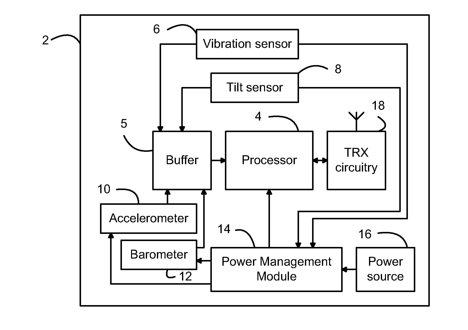
[0033]a fall detection system 2 is shown in FIG. 2. The fall detection system 2 comprises a processor 4 connected to a buffer 5, that is itself connected to a plurality of sensors 6, 8, 10 and 12. At least one of the sensors is a passive sensor, and in this embodiment, the passive sensor is a vibration sensor 6 that detects motion of the user of the fall detection system 2 and can be a simple “switch-type” sensor. A further passive sensor is the tilt sensor 8, which detects the tilt of the fall detection system 2, and in particular the change in orientation of the user that can occur in a fall. In some embodiments of the invention, the tilt sensor 8 can be omitted from the fall detection system 2.

[0034]The remaining sensors 10, 12 in this fall detection system are active sensors, which means that they require electrical power to operate. Sensor 10 is an accelerometer that measures the accelerations experienced by the user (such as a downward movement and an impact), and sensor 12 is...

second embodiment

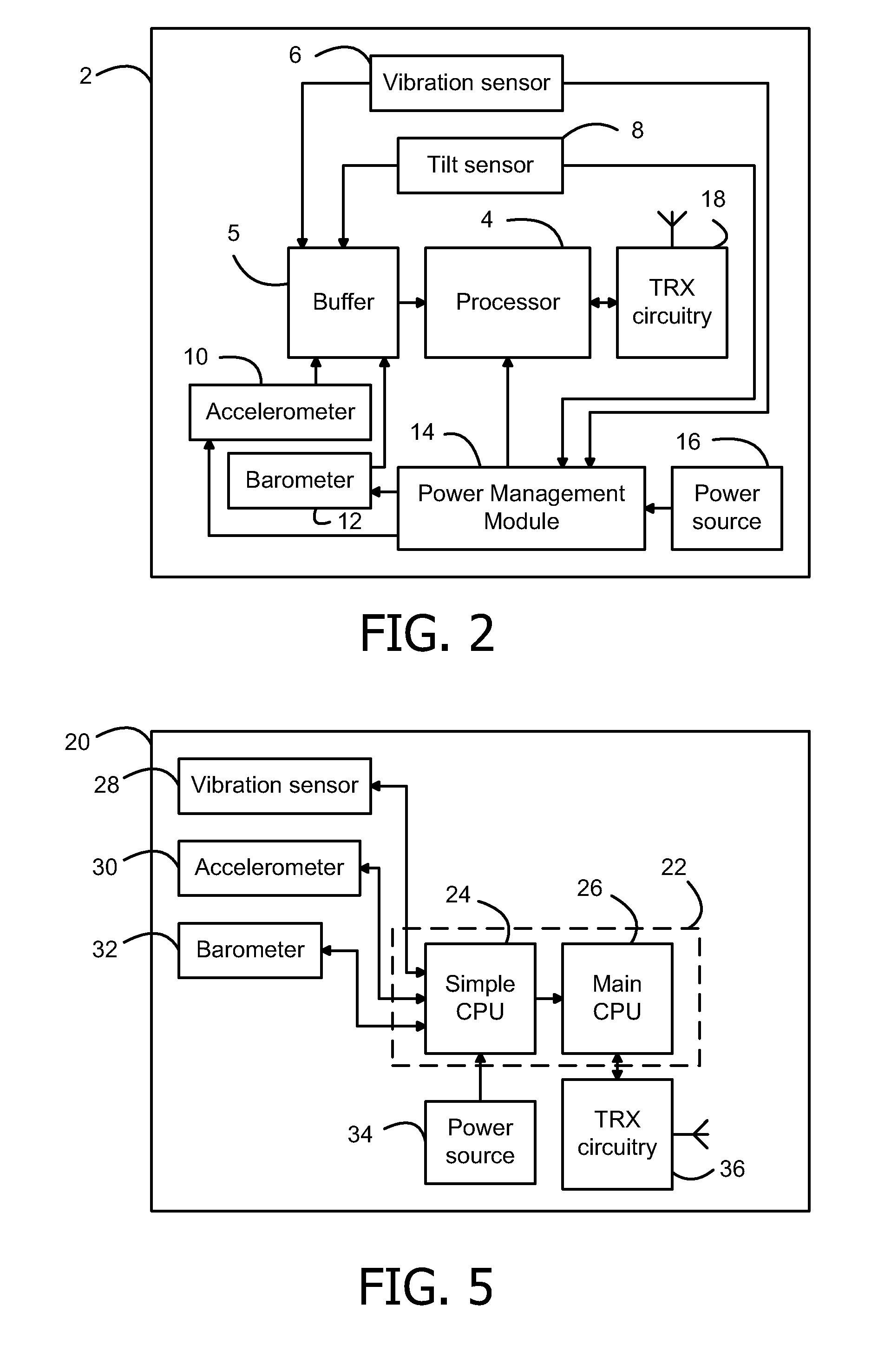
[0048]FIG. 5 shows a fall detection system in accordance with the invention. In this embodiment, it is necessary for the sensors to periodically take measurements, so that the processor has historic measurements available for when it executes the fall detection algorithm.

[0049]The system 20 according to this second embodiment comprises a processing unit 22, which includes a simple processor 24 and a main processor 26. The system 20 comprises a plurality of sensors 28, 30 and 32, namely a passive vibration sensor, an accelerometer and a barometer respectively. It will be appreciated that this system 20 could further include a tilt sensor. Each of the sensors 28, 30 and 32 is connected to the simple processor 24.

[0050]The power source 34 for the system 20 is also connected to the simple processor 24, and the simple processor 24 selectively provides this power to the main processor 26, accelerometer 30 and barometer 32. Transceiver circuitry 36 is connected to the main processor 26. It...


PUM


Abstract

There is provided a fall detection system, comprising a passive vibration sensor; one or more other sensors for detecting respective characteristics of a fall; and a processor for analyzing measurements from the one or more other sensors to determine if a fall has occurred; wherein the system is configured to selectively provide power to the one or more other sensors and/or processor in response to the passive vibration sensor detecting motion of a user of the fall detection system.

Description


Claims


Application Information

Patent Timeline
Owner KONINKLIJKE PHILIPS ELECTRONICS NV
Why Eureka
Try Eureka