Heat pump with microchannel heat exchangers as both outdoor and reheat exchangers

a heat exchanger and microchannel technology, applied in the field of heat pumps, can solve the problems of inability to accumulate in a microchannel heat exchanger with a much smaller internal volume, disadvantage on occasion, and excessive charge which may migrate from other refrigerant system components

Inactive Publication Date: 2011-04-07
CARRIER CORP
View PDF46 Cites 31 Cited by
  • Summary
  • Abstract
  • Description
  • Claims
  • Application Information

AI Technical Summary

Benefits of technology

[0009]A heat pump has a compressor for delivering a compressed refrigerant to a reversing refrigerant flow control device. The reversing refrigerant flow control device selectively delivers refrigerant to an outdoor heat exchanger in a cooling mode, and to an indoor heat exchanger in a heating mode. Refrigerant from an outdoor heat exchanger passes through an expansion device to an indoor heat exchanger

Problems solved by technology

Although this is an advantage, it may become a disadvantage on occasion.
As an example, the excessive charge which may migrate from other refrigerant system components at continuously changing environmental conditions and modes of operation and is typically stored in an outdoor heat exchanger having large internal volume, such as a round tube and plate fin heat exchanger, will not be able to accumulate in a microchannel heat exchanger having much smaller internal volume.
The smaller internal volume of microchannel heat exchangers makes them extremely sensitive to ov

Method used


Image

  • Heat pump with microchannel heat exchangers as both outdoor and reheat exchangers
  • Heat pump with microchannel heat exchangers as both outdoor and reheat exchangers
  • Heat pump with microchannel heat exchangers as both outdoor and reheat exchangers

Examples


Embodiment Construction

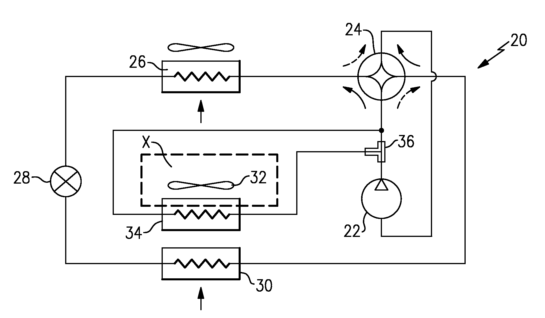
[0015]FIG. 1 shows a heat pump refrigerant system 20 wherein a compressor 22 compresses a refrigerant and delivers it through a reversing refrigerant flow control device such as a four-way reversing valve 24. The four-way reversing valve 24 routes the compressed refrigerant to an outdoor heat exchanger 26 when the heat pump refrigerant system 20 is in a cooling mode of operation. Downstream of the outdoor heat exchanger 26, the refrigerant passes through an expansion device 28, and then through an indoor heat exchanger 30. As known, if the heat pump 20 is operated in a heating mode, the four-way reversing valve 24 is controlled to route the refrigerant first to the indoor heat exchanger 30, the expansion device 28, and then to the outdoor heat exchanger 26. In both modes of operation, the refrigerant is returned to the four-way reversing valve 24 and routed back to the compressor 22. The expansion device 28 can be a single bi-directional expansion device or a pair of unidirectional ...


PUM


Abstract

A heat pump refrigerant system has a compressor for delivering a compressed refrigerant to a reversing refrigerant flow control device. The reversing refrigerant flow control device selectively delivers refrigerant to an outdoor heat exchanger in a cooling mode of operation, and to an indoor heat exchanger in a heating mode of operation. Refrigerant from an outdoor heat exchanger passes through an expansion device to an indoor heat exchanger in a cooling mode, and from the indoor heat exchanger through an expansion device and to the outdoor heat exchanger in a heating mode. A reheat circuit includes a reheat heat exchanger positioned to be in the path of air delivered over the indoor heat exchanger and into an environment to be conditioned. The reheat heat exchanger and outdoor heat exchanger both are provided by microchannel heat exchangers. The reheat circuit is utilized to minimize or prevent refrigerant charge migration while operating at a wide spectrum of environmental conditions or switching between modes of operation.

Description

BACKGROUND OF THE INVENTION[0001]One type of refrigerant system is a heat pump. A heat pump can be utilized to heat air being delivered into an environment to be conditioned, or to cool and typically dehumidify the air delivered into the indoor environment. In a basic heat pump, a compressor compresses a refrigerant and delivers it downstream through a refrigerant flow reversing device, typically a four-way reversing valve. The refrigerant flow reversing device initially routes the refrigerant to an outdoor heat exchanger, if the heat pump is operating in a cooling mode, or to an indoor heat exchanger, if the heat pump is operating in a heating mode. From the outdoor heat exchanger, the refrigerant passes through an expansion device, and then to the indoor heat exchanger, in the cooling mode of operation. In the heating mode of operation, the refrigerant passes from the indoor heat exchanger to the expansion device and then to the outdoor heat exchanger. In either case, the refriger...

Claims


Application Information

Patent Timeline
IPC IPC(8): F25B13/00
CPCF24F3/153F25B13/00F25B2313/021F28D1/05391F25B2313/02742F25B2400/06F25B2313/02741
Inventor TARAS, MICHAEL F.LIFSON, ALEXANDER
Owner CARRIER CORP
Why Eureka
Try Eureka