Cutting apparatus

a cutting apparatus and guillotine-type technology, applied in the direction of band saws, manufacturing tools, transportation and packaging, etc., can solve the problems of lowering operating efficiency, and achieve the effect of simplifying the configuration of the apparatus and reducing its cos

Active Publication Date: 2011-04-07
SATO HLDG CORP
View PDF13 Cites 2 Cited by
  • Summary
  • Abstract
  • Description
  • Claims
  • Application Information

AI Technical Summary

Benefits of technology

[0012]A guide surface formed on the cover is configured to guide the printed medium between the fixed blade and the movable blade when the lid portion is closed. In this configuration, the cover which covers the fixed blade when the lid portion is released, can be used as a guide configured to guide the printed medium when the lid portion is closed, simplifying the configuration of the apparatus and reducing its cost.

Problems solved by technology

Therefore, aforesaid operations, such as the replacement or the cleaning, are required to be performed while keeping away from the exposed fixed blade, which results in a problem of lowering of operating efficiency.

Method used


Image

  • Cutting apparatus
  • Cutting apparatus
  • Cutting apparatus

Examples


Embodiment Construction

[0019]Referring now to the drawings, an embodiment of the present invention will be described.

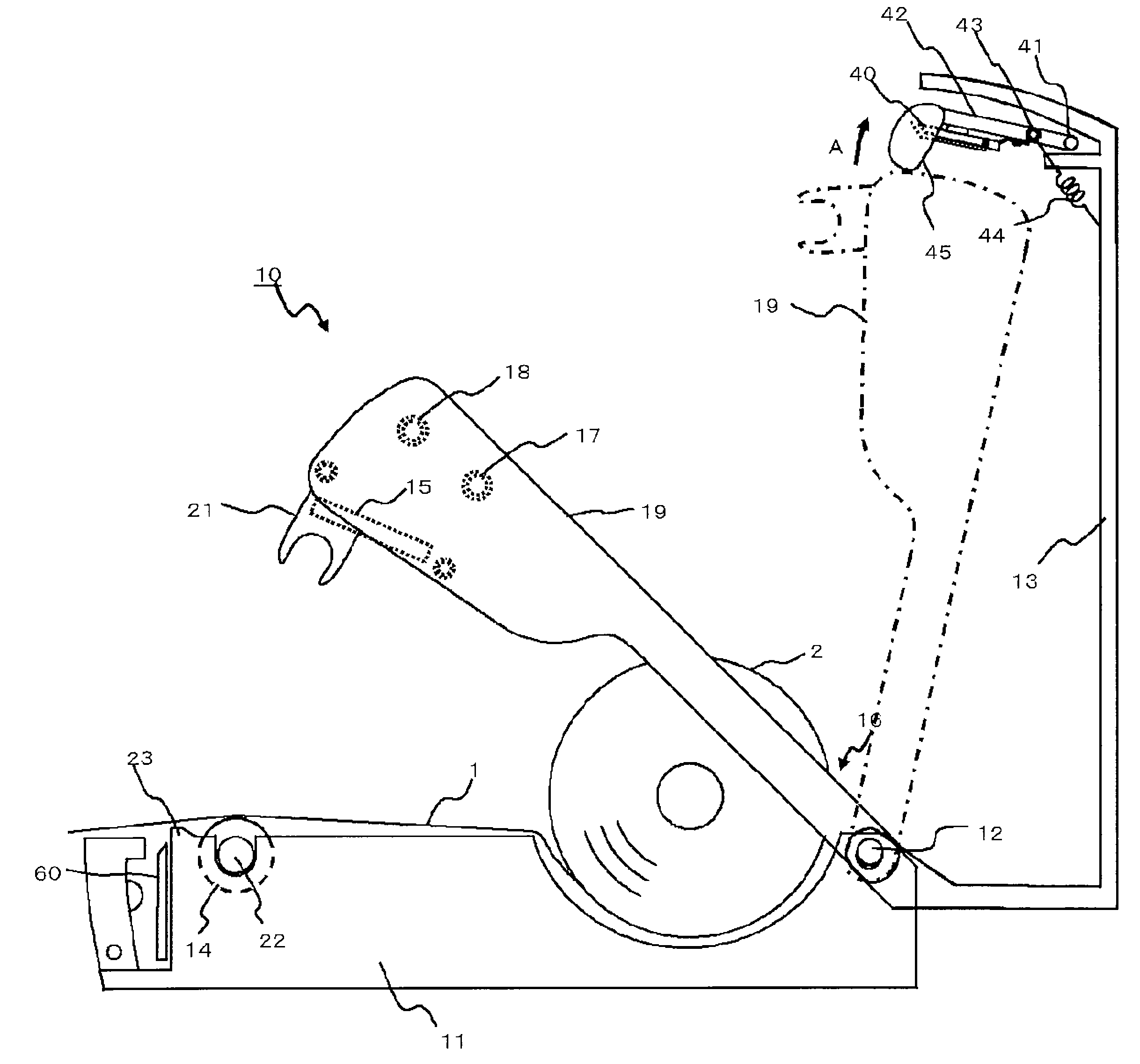
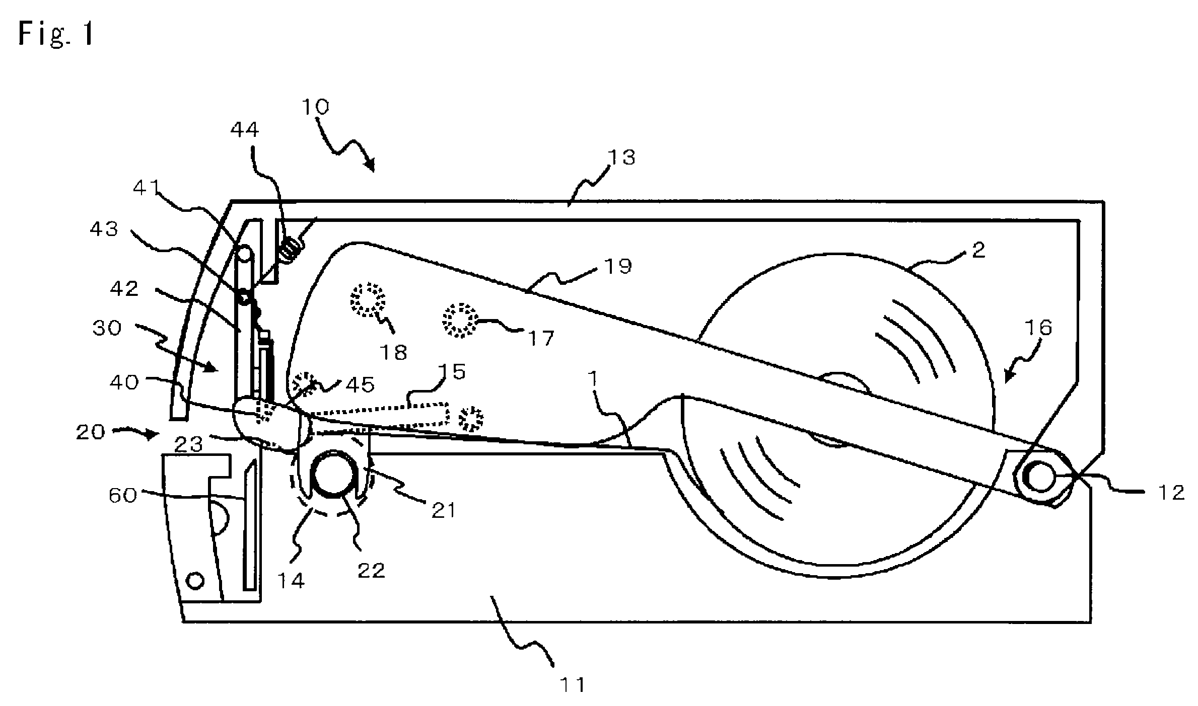
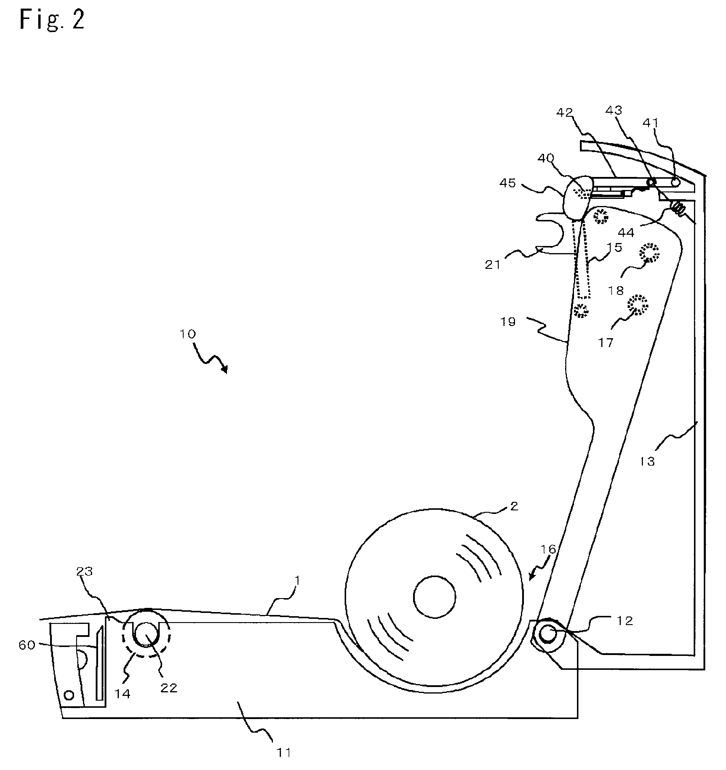
[0020]A cutting apparatus 30 according to an embodiment is configured to cut a printed medium 1 which had been printed by a printer 10. The cutting is caused by an engagement between a fixed blade 40 and a movable blade 60 which is movable toward the fixed blade 40. Referring to FIG. 1 to FIG. 3, the cutting apparatus 30 is integrated into a lid portion 13. The lid portion 13 is supported by a supporting shaft 12 of a casing body 11. The lid is capable of opening and closing an upper part of the casing body 11. The fixed blade 40 is mounted in the lid portion 13 and the movable blade 60 is mounted in the casing body 11.

[0021]Referring to FIG. 1, the printer 10 includes a platen roller 14 and a thermal head 15 opposing the roller 14 in such a manner that a surface (hereinafter referred to as a “printing surface”) having a plurality of heat-generating members formed in the widthwise direction...


PUM

PropertyMeasurementUnit
widthaaaaaaaaaa
areaaaaaaaaaaa
urging forceaaaaaaaaaa

Abstract

A cutting apparatus which avoids exposing a fixed blade mounted in a lid portion even when the lid portion is opened. A fixed blade 40 is arranged so that a blade surface 40b faces the upstream side in the direction of transport of a printed medium 1. A cover 48 is slidably mounted on the fixed blade 40, is configured to cover a cutting edge line 40a of the fixed blade 40 from the side of the blade surface 40b when a lid portion 13 is released, and may be slid toward a root of the fixed blade 40 to expose the cutting edge line 40a of the fixed blade 40 when the lid portion 13 is closed.

Description

CROSS-REFERENCE TO RELATED APPLICATIONS[0001]The present application is a 35 U.S.C. §§371 national phase conversion of PCT / JP2008 / 071853, filed Dec. 2, 2008, which claims priority of Japanese Application No. 2008-167798, filed Jun. 26, 2008, the contents of which are incorporated by reference herein. The PCT International Application was published in the Japanese language.TECHNICAL FIELD[0002]The present invention relates to a guillotine-type cutting apparatus including a fixed blade and a movable blade and, in particular, to a guillotine-type cutting apparatus integrated into a printer in such a manner that the movable blade is mounted in a casing body of a printer, and the fixed blade of the guillotine-type cutting apparatus is mounted in a lid portion which is movable with respect to the casing body.BACKGROUND ART[0003]In the related art, a printer is known having a cutting apparatus configured in such a manner that a movable blade of a guillotine-type cutting apparatus is mounte...

Claims


Application Information

Patent Timeline
Patent Type & Authority Applications(United States)
IPC IPC(8): B26D7/22
CPCB26D1/085B26D7/00B26D7/22B65H2601/321B65H35/0086B65H35/06B65H2407/10B41J11/70Y10T83/96B41J11/706
Inventor HOSONO, SHINICHIRO
Owner SATO HLDG CORP
Why Eureka
Try Eureka