Centerless grinding apparatus and centerless grinding method

a centerless grinding and centerless technology, applied in the direction of grinding machine components, grinding machine components, manufacturing tools, etc., can solve the problem of not being able to simultaneously grind both the outer diameter surface and the end surface of the work, and achieve the effect of reducing processing costs, simplifying the configuration of the apparatus, and shortening the time period required for the grinding process

Inactive Publication Date: 2006-01-17
NSK LTD
View PDF11 Cites 2 Cited by
  • Summary
  • Abstract
  • Description
  • Claims
  • Application Information

AI Technical Summary

Benefits of technology

[0024]In the aforesaid configuration, at the time of grinding the outer diameter surface of the work by the outer diameter surface grinding wheel while supporting the outer diameter surface of the work by the outer diameter surface grinding wheel and the regulating wheel, the end surface grinding of the work is carried out by utilizing that the movement of the work in the axial direction thereof is suppressed. Thus, the outer diameter surface and the end surface of the work can be ground simultaneously without changing the positions for grasping the work or indexing the work to different grinding processing positions. According to the invention, the configuration of the apparatus can be simplified, a time period required for the grinding process can be shortened and the processing cost can be reduced. Further, it becomes possible to process with a higher accuracy.

Problems solved by technology

According to the apparatus described in JP-A-6-339842, although both the inner diameter surface and the end surface of the work can be processed with one-time chucking, it is impossible to simultaneously grind both the outer diameter surface and the end surface of the work since a chuck interferes with the grinding wheel.

Method used


Image

  • Centerless grinding apparatus and centerless grinding method
  • Centerless grinding apparatus and centerless grinding method
  • Centerless grinding apparatus and centerless grinding method

Examples


first embodiment

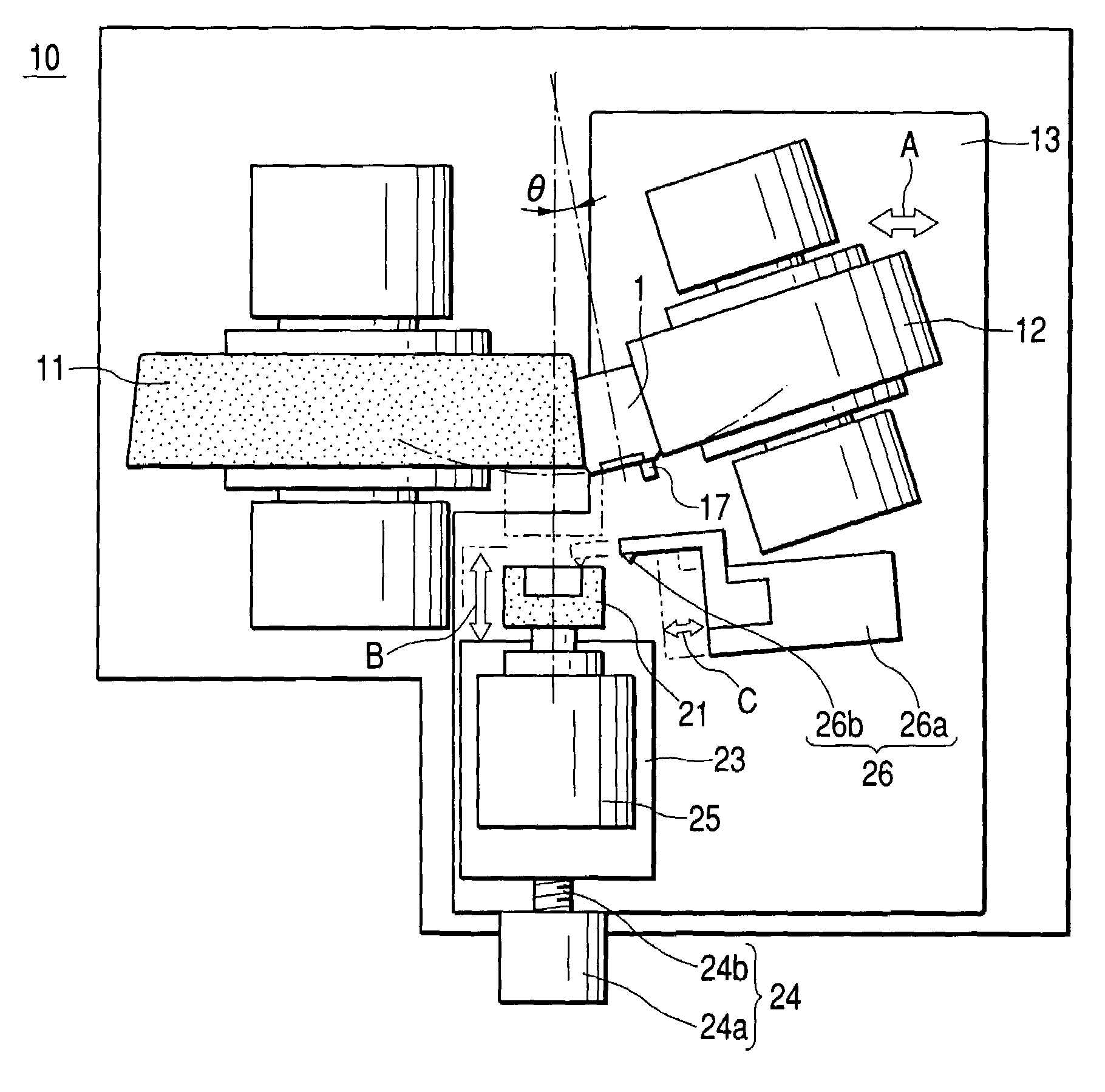
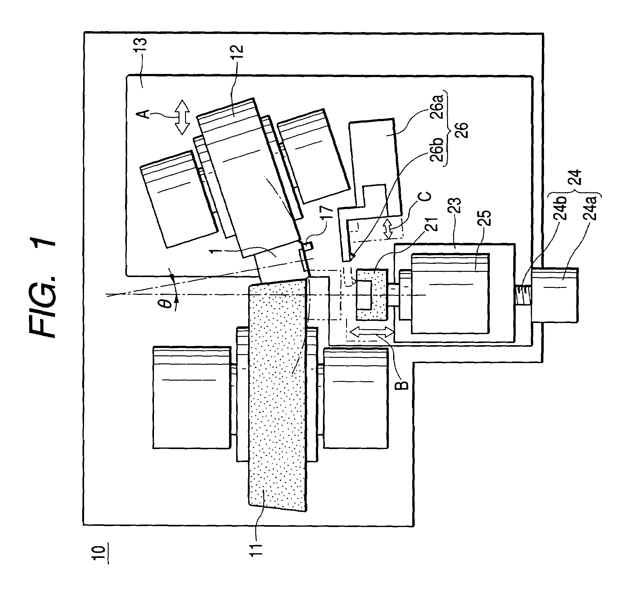
[0037]FIG. 1 is a schematic plan view of a centerless grinding apparatus 10 according to the invention. The centerless grinding apparatus 10 is suitable for grinding a work such as a conical roller 1 etc. A first grinding mechanism for grinding the outer diameter surface of a work 1 includes an outer diameter surface grinding wheel 11 formed in a disc shape, a regulating wheel 12, an outer diameter surface cutting table 13 for approaching and separating the regulating wheel 12 to and from the outer diameter surface grinding wheel 11, respectively, a supporting blade for supporting the work 1 from the lower side thereof (support the work 1 from the rear side of the drawing sheet) and a dressing device (not shown) for the outer diameter surface grinding wheel 11 and the regulating wheel 12. These constituent elements are also provided at the usual in-feed centerless grinding machine.

[0038]The centerless grinding apparatus 10 according to the embodiment includes a second grinding mecha...

second embodiment

[0059]Next, a centerless grinding apparatus 40 according to the invention will be explained based on FIGS. 5A and 5B. Now, in the embodiment explained below, parts etc. having the similar constructions and operations to the parts etc. described above are marked with the same or corresponding references, and therefor the explanations thereof are simplified or omitted.

[0060]FIG. 5A is a schematic plan view showing the main portion of the centerless grinding apparatus 40. FIG. 5B is a diagram seen from an arrow B direction in FIG. 5A. The outer periphery of a regulating wheel 42 is formed in a conical shape (or a hourglass-shape) like the outer periphery of an outer diameter surface grinding wheel 41. A work (conical roller) 1 is disposed between the outer periphery of the outer diameter surface grinding wheel 41 and the outer periphery of the regulating wheel 42. A cup grinding wheel 21 serving as an end surface grinding wheel and an end surface stopper 47 are disposed in a substantia...

third embodiment

[0068]Usually, since the outer diameter surface grinding wheel 51 rotates in a downward posture and the work 1 also rotates in a downward posture. Thus, in the third embodiment, an upward friction force occurs on the end surface stopper 17, and this friction force serves to float the work 1 from the supporting blade. However, such a phenomenon does not raise any problem as long as the grinding condition is selected suitably.

[0069]Although the friction force becomes downward when the rotation directions of the work 1 and the outer diameter surface grinding wheel 51 are reversed, the operations change in such a manner that the grinding force becomes upward or the entering way of coolant to the grinding point changes.

[0070]Next, a centerless grinding apparatus 60 according to the fourth embodiment of the invention will be explained based on FIG. 9. Although this embodiment is almost same in its construction as the third embodiment, this embodiment differs from the third embodiment in t...


PUM

PropertyMeasurementUnit
outer diameteraaaaaaaaaa
diameteraaaaaaaaaa
distanceaaaaaaaaaa

Abstract

A centerless grinding apparatus (10) includes an outer diameter surface grinding wheel (11) for grinding the outer diameter surface of a work (1) of a substantially cylindrical shape, a regulating wheel (12) for supporting the outer diameter surface of the work (1) in conjunction with the outer diameter surface grinding wheel (11) and an end surface grinding wheel (21) for grinding the end surface of the work (1). The end surface grinding wheel (21) grinds the end surface of the work (1) while the outer diameter surface grinding wheel (11) grinds the outer diameter surface of the work (1) in a state that the work (1) is disposed between the outer diameter surface grinding wheel (11) and the regulating wheel (12).

Description

BACKGROUND OF THE INVENTION[0001]1. Field of the Invention[0002]The present invention relates to an in-feed type centerless grinding apparatus.[0003]2. Description of the Related Art[0004]For example, the centerless grinding apparatuses used for manufacturing the rollers of rolling bearings are classified into an in-feed type, a through-feed type and a tangential-type.[0005]According to the in-feed type, a work is ground in a predetermined shape by radially feeding a grinding wheel or a regulating wheel in a state where the work is set in a grinding space between the rotating grinding wheel and the rotating regulating wheel.[0006]Conventionally, the outer diameter surface and the end surface of a work are ground by separate grinding apparatuses, respectively, in a manner that the work subjected to the heat treatment is first ground at its outer diameter surface and then ground at its end surface. Further, as to a work required for a high accuracy, in order to obtain the sufficient a...

Claims


Application Information

Patent Timeline
Patent Type & Authority Patents(United States)
IPC IPC(8): B24B49/00B24B5/18B24B5/01B24B5/22B24B5/24B24B7/16B24B27/00B24B53/047
CPCB24B5/01B24B5/22B24B27/0076B24B7/16B24B5/24
Inventor KAMAMURA, YUKOIWANAMI, HIROYUKI
Owner NSK LTD
Why Eureka
Try Eureka