Surface profile detection apparatus of burden in blast furnace and operation method

Pending Publication Date: 2021-08-19
WADECO
View PDF0 Cites 0 Cited by
  • Summary
  • Abstract
  • Description
  • Claims
  • Application Information

AI Technical Summary

Benefits of technology

[0045]According to the present invention, the detection apparatus has a simple apparatus configuration and can detect a deposit

Problems solved by technology

Therefore, when the lance is inserted long in the furnace, the lance is sagged downward by its own weight, so that the lance cannot be taken out from the furnace.
It is also necessary to separately provide a drive unit for moving the lance 10, so that the facility cost and the opera

Method used


Image

  • Surface profile detection apparatus of burden in blast furnace and operation method
  • Surface profile detection apparatus of burden in blast furnace and operation method
  • Surface profile detection apparatus of burden in blast furnace and operation method

Examples


Example

First Embodiment

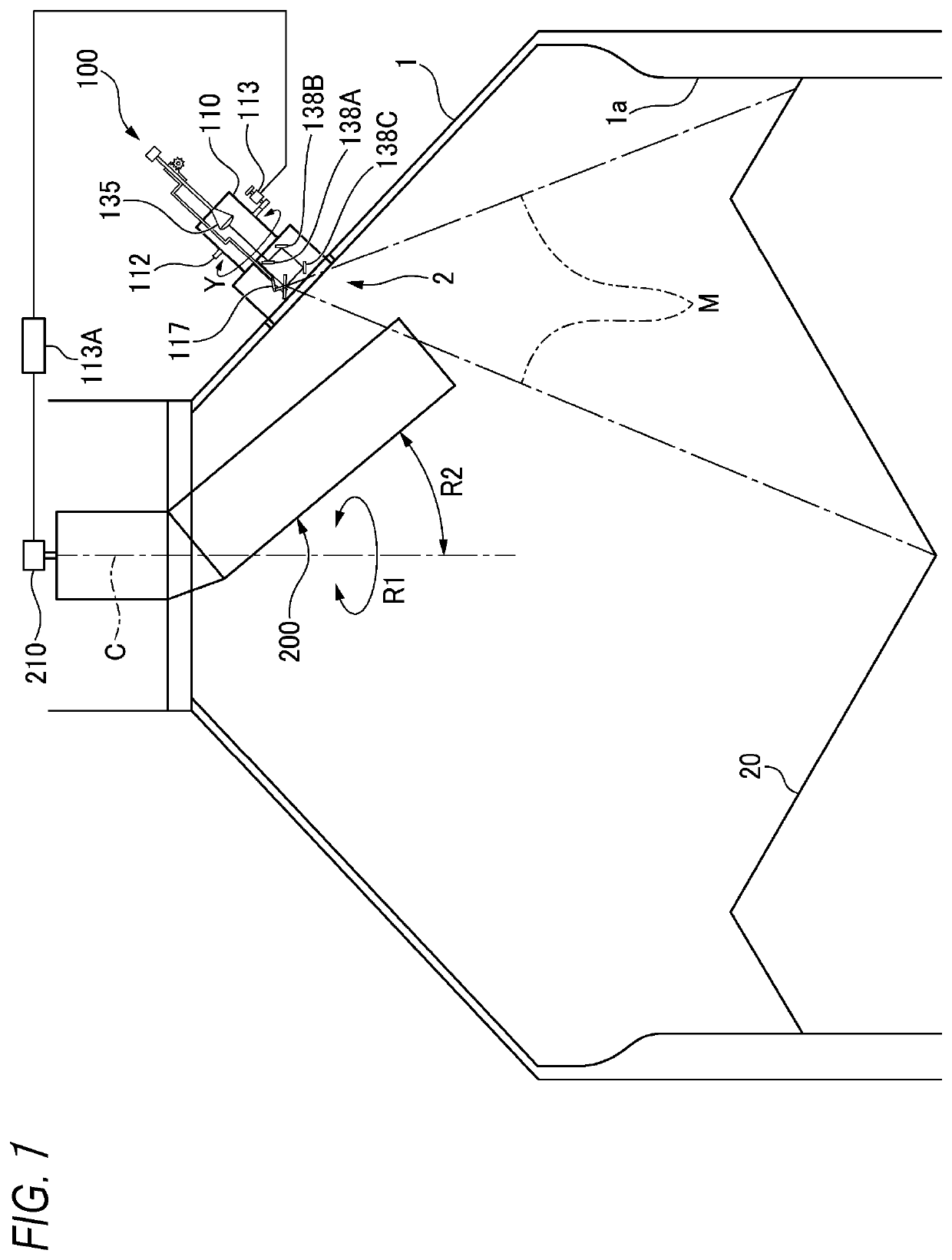
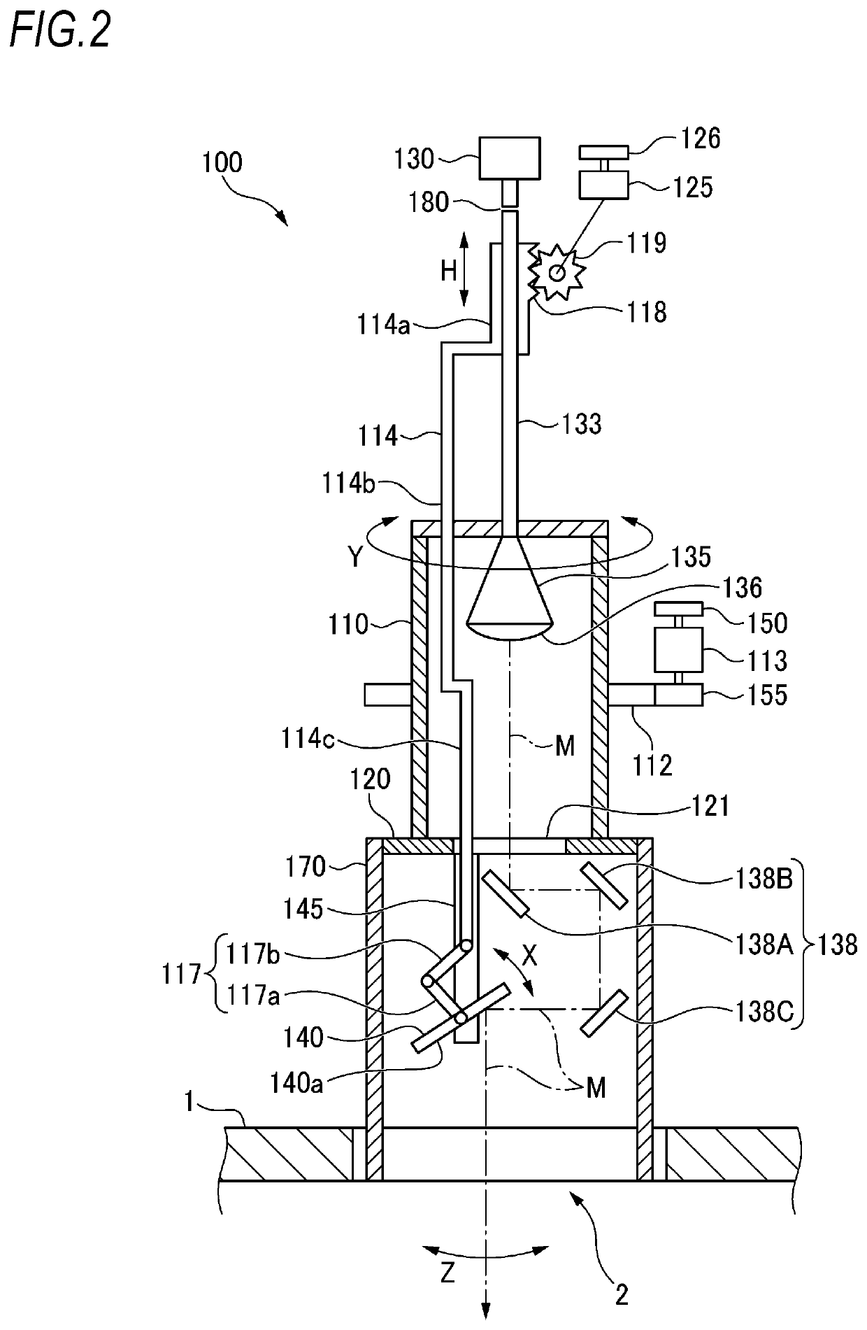
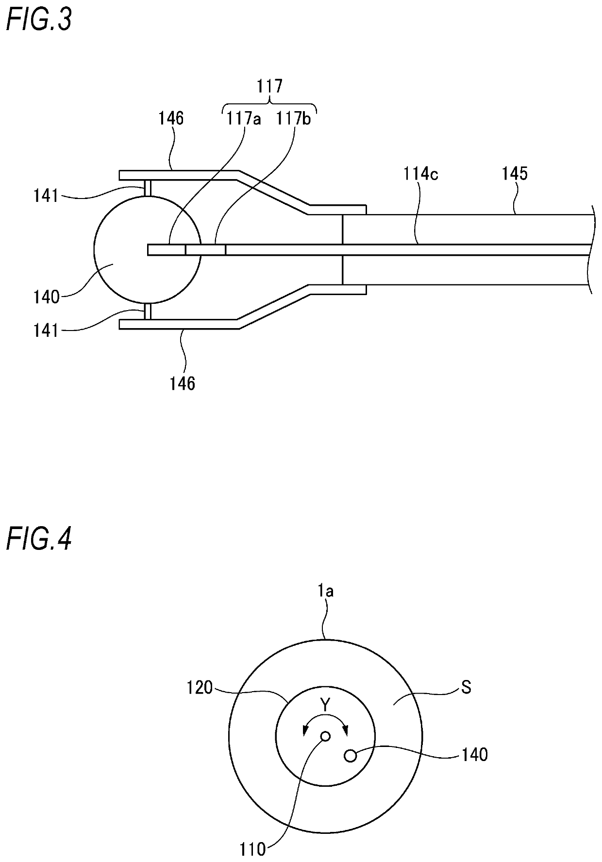
[0064]FIG. 1 is a schematic sectional view taken along an axis line of a blast furnace, depicting a state in which the detection apparatus of the present invention is mounted to the blast furnace, and FIGS. 2 and 3 depict a configuration of the detection apparatus.

[0065]As shown in FIG. 1, a blast furnace 1 is supplied with iron ore, coke, limestone and the like, which are burden 20, by a shooter 200. The shooter 200 is configured to turn in a direction denoted with a reference sign R1 about an axis line C of the blast furnace 1, and to control a drop position of the burden 20 by changing an inclination angle R2 relative to the axis line C. The shooter 200 may be a well-known shooter, and a turning angle in the R1 direction is detected by an encoder 210. The burden 20 dropped from the shooter 200 is deposited in the furnace of the blast furnace 1.

[0066]An opening part 2 is formed in the vicinity of a furnace top of the blast furnace 1, and a detection apparatus 100 i...

Example

Second Embodiment

[0102]FIG. 6 depicts a second embodiment of the detection apparatus 100. As shown in FIG. 6, a horn length of the antenna 135 may be lengthened. The horn length of the antenna 135 is lengthened, so that it is possible to handle the transmission and reception of the millimeter wave without using the dielectric lens 136 of the first embodiment, and the horn length is adjusted so as to be suitable for the transmission and reception of the millimeter wave.

[0103]The antenna surface of the antenna 135 can extend up to a place near the opening 121 of the rotating plate 120. In association with this, the intermediate part 114b of the coupling rod 114 may be formed to extend through the opening 121 of the rotating plate 120 and to couple to the second link 117b of the link mechanism 117 without the lower end portion 114c shown in FIG. 2. Note that, also in the first embodiment, the lower end portion 114c may be omitted.

[0104]Except that the horn length of the antenna 135 is ...

Example

Third Embodiment

[0107]FIG. 7 is a schematic sectional view taken along the axis line of the blast furnace depicting a third embodiment of the detection apparatus of the present invention, showing a state in which the detection apparatus is mounted to the blast furnace, and FIGS. 8 and 9 depict a configuration of the detection apparatus.

[0108]As shown in FIG. 7, the blast furnace 1 is supplied with a burden 20 such as iron ore, coke and limestone by a shooter 200. The shooter 200 is configured to turn in a direction denoted with a reference sign R1 about an axis line C of the blast furnace 1, and to control a drop position of the burden 20 by changing an inclination angle R2 relative to the axis line C. The shooter 200 may be a well-known shooter, and a turning angle in the R1 direction is detected by an encoder 210. The burden 20 dropped from the shooter 200 is deposited in the furnace of the blast furnace 1.

[0109]An opening part 2 is formed in the vicinity of a furnace top of the b...


PUM

PropertyMeasurementUnit
Angleaaaaaaaaaa
Surfaceaaaaaaaaaa

Abstract

Provided is a surface profile detection apparatus of a burden in a blast furnace having a simple apparatus configuration and capable of detecting a deposited state of the burden while a shooter is turning and enabling an operation close to a theoretical deposition profile. The surface profile detection apparatus of a burden in a blast furnace includes a rotating plate mounted immediately above an opening part of the blast furnace and configured to rotate about an opening center of the opening part as a central axis, a rotating means for rotating the rotating plate, and a transmission and reception means for transmitting a detection wave such as a microwave or a millimeter wave in a linear shape along a diametrical direction of the rotating plate and receiving the detection wave. The surface profile detection apparatus performs transmission and reception in a direction orthogonal to a rotating direction of the rotating plate while rotating the rotating plate in synchronization with turning of the shooter so that transmission of the detection wave is not interrupted.

Description

TECHNICAL FIELD[0001]The present invention relates to a detection apparatus configured to detect a surface profile of iron ore, coke and limestone (hereinbelow, collectively referred to as “burden”) in a blast furnace. The present invention also relates to a method of supplying the burden and performing a stable operation, based on the surface profile of the burden.BACKGROUND ART[0002]In a blast furnace, when a deposited state of burden is optimized, a gas flow in the furnace becomes stable, so that the fuel cost can be saved and the service life of a furnace body can be extended. In order to obtain an optimized deposited state, it is necessary to accurately measure a surface profile of the burden in a short time, and to supply the burden so as to be a theoretical deposited state, i.e., “theoretical deposition profile” obtained in advance. In a general conventional method of measuring the surface profile, as shown in FIG. 16, a detection wave M1 is emitted toward a surface of a burd...

Claims


Application Information

Patent Timeline
IPC IPC(8): C21B7/24G01B15/04C21B5/00
CPCC21B7/24C21B5/00G01B15/04C21B5/006C21B5/008F27D21/0028F27B1/28
Inventor KAYANO, HAYAE
Owner WADECO
Why Eureka
Try Eureka