Eureka AIR delivers breakthrough ideas for toughest innovation challenges, trusted by R&D personnel around the world.

Surface detection apparatus for blast furnace

Active Publication Date: 2019-08-15
WADECO
View PDF0 Cites 0 Cited by
  • Summary
  • Abstract
  • Description
  • Claims
  • Application Information

AI Technical Summary

Benefits of technology

The surface detection apparatus described in this patent text allows for the easy and quick fixation of an antenna to a container, which eliminates the need for additional mechanisms to rotate the antenna and prevent co-rotation of the transceiver. This simplifies the configuration of the apparatus and reduces the length of the waveguide needed to connect the antenna to the transceiver. Overall, this makes it easier and more efficient to detect and locate objects using the surface detection apparatus.

Problems solved by technology

However, since the lance is linearly moved, a profile of an entire surface of the burden is not obtained.
Therefore, when the lance is inserted in the furnace for a long period of time, it is sagged downward by its own weight, so that the lance cannot be taken out from the furnace.
Also, it is necessary to separately provide a drive unit for moving the lance, so that the facility cost and the operating cost increase.
In addition, it is not possible to perform the charging operation during the profile measurement, so that it is not possible to perform the rapid charging operation, in correspondence to the measured profile.

Method used


Image

  • Surface detection apparatus for blast furnace
  • Surface detection apparatus for blast furnace
  • Surface detection apparatus for blast furnace

Examples


Embodiment Construction

[0039]Hereinafter, the present invention will be described in detail with reference to the drawings.

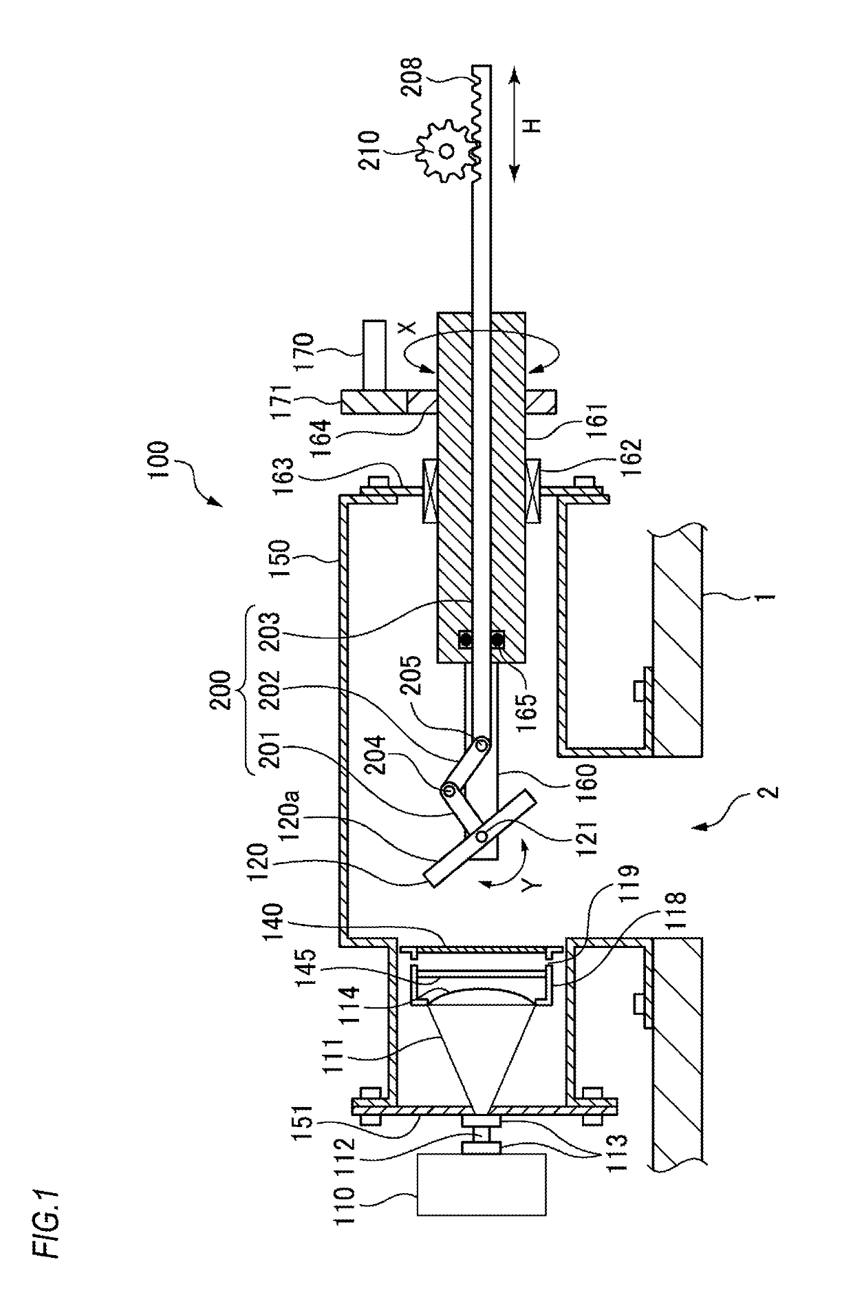
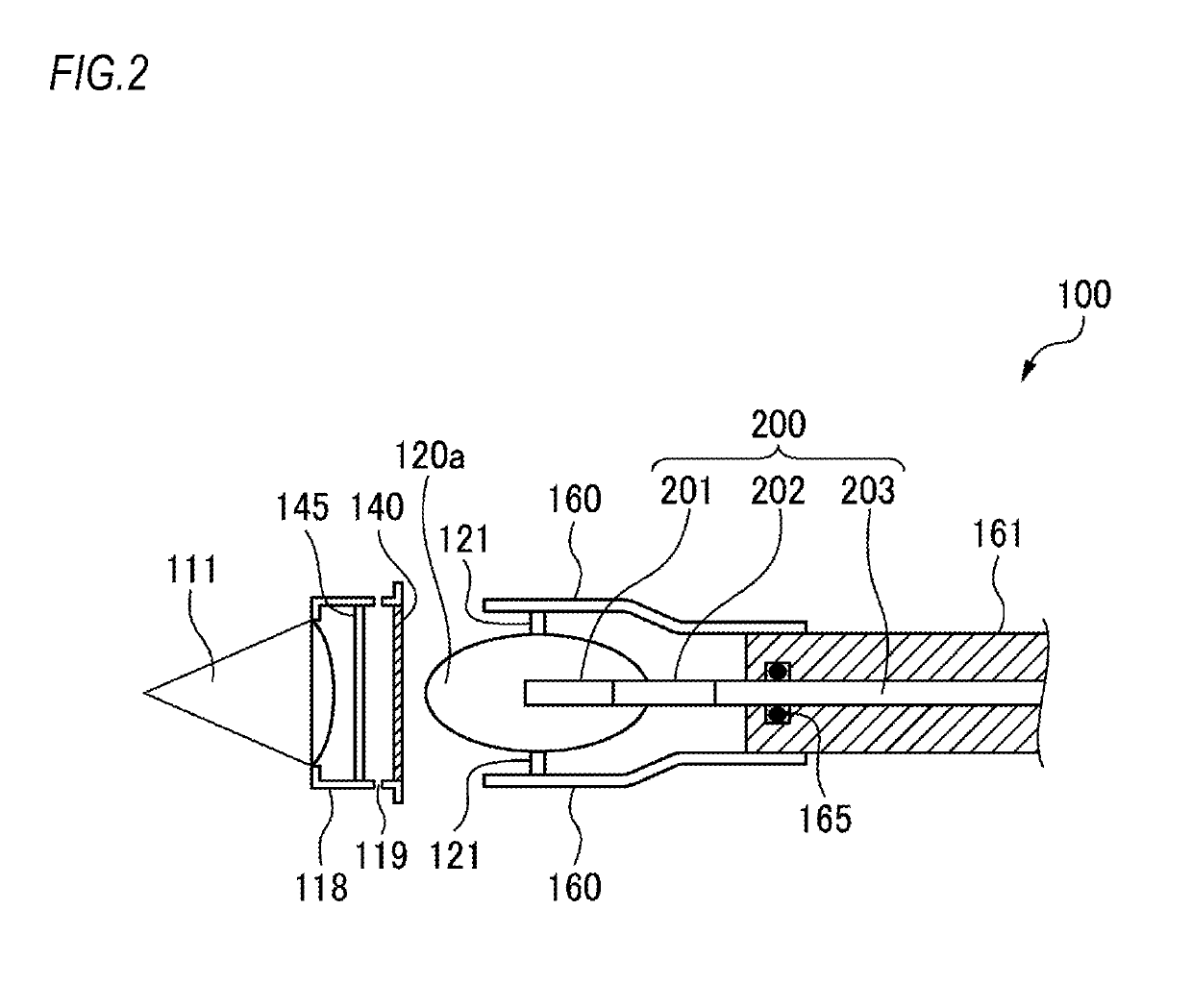
[0040]FIG. 1 is a sectional view depicting an entire structure of a surface detection apparatus of the present invention, and FIG. 2 is a plan view depicting a periphery of an antenna and a reflection plate. As shown, a container 150 is attached to an opening portion 2 of a blast furnace 1. The container 150 has a bottom a part of which is opened in correspondence to the opening portion 2, and is attached continuously to the opening portion 2.

[0041]One side (a left end portion, in FIG. 1) of the container 150 is opened, and the opened portion is closed by an antenna attachment wall 151. The antenna attachment wall 151 is detachably attached to the container 150 by a bolt and the like. An antenna 111 is attached to the antenna attachment wall 151. Also, a transceiver 110 for detection wave is coupled to the antenna 111. In the meantime, as the detection wave, a microwave or a millimete...


PUM


Abstract

A surface detection apparatus for a blast furnace is provided. An antenna is fixed to a side of a container attached to an opening portion of the blast furnace and having a bottom surface opened in correspondence to the opening portion. A reflection plate is disposed in the container immediately above the opening portion so as to face the opening portion and the antenna. A tilt angle varying mechanism and a rotation mechanism for the reflection plate are configured as a double pipe structure and are provided at an anti-antenna side of the reflection plate.

Description

TECHNICAL FIELD[0001]The present invention relates to an apparatus configured to transmit a detection wave such as a microwave or a millimeter wave into a blast furnace, and to receive the detection wave reflected by iron ore and coke (burden) charged in the furnace, thereby detecting a surface profile of the burden.BACKGROUND ART[0002]In a blast furnace, an operation is performed while alternately charging iron ore and coke. However, when iron ore and coke (hereinafter referred to as burden) are accumulated as appropriate, a gas flow in the furnace becomes stable, so that the fuel cost can be saved and the service life of the furnace can be increased. To this end, it is necessary to accurately measure a surface profile of the burden in a short time, and to appropriately charge the burden in correspondence to a change in furnace situation.[0003]In a general conventional method of measuring the surface profile, a lance is inserted into the blast furnace from a sidewall of the blast f...

Claims


Application Information

Patent Timeline
IPC IPC(8): C21B7/24G01F23/284G01S7/03G01S13/88
CPCC21B7/24G01F23/284G01S7/03G01S13/88C21B5/008F27B1/28F27D21/0028F27D2021/0042F27D2019/0003G01S13/42
Inventor KAYANO, HAYAEKUROSE, KENJI
Owner WADECO
Why Eureka
Eureka Blog
Learn More