Imaging apparatus and imaging method

a technology of imaging apparatus and imaging method, which is applied in the field of imaging techniques, can solve the problems of unavoidable events and the generation of complex conjugate noise in images, and achieve the effect of simple apparatus configuration

Active Publication Date: 2020-03-26
DAINIPPON SCREEN MTG CO LTD
View PDF0 Cites 0 Cited by
  • Summary
  • Abstract
  • Description
  • Claims
  • Application Information

AI Technical Summary

Benefits of technology

[0016]As described above, according to the invention, the influence of the complex conjugate noise due to the container wall surface can be eliminated near the position corresponding to the focal depth of the objective optical system. The above effect can be obtained if there is a function of setting the optical path length of the reference light in conjunction with the setting of the focal depth of the objective optical system. Therefore, a tomographic image having the influence of the complex conjugate noise eliminated therefrom can be obtained by a simple apparatus configuration.
[0017]The above and further objects and novel features of the invention will more fully appear from the following detailed description when the same is read in connection with the accompanying drawing. It is to be expressly understood, however, that the drawing is for purpose of illustration only and is not intended as a definition of the limits of the invention.

Problems solved by technology

In the FD-OCT technique, it is known that noise called complex conjugate noise is generated in an image of an imaging object.
This unavoidably occurs due to the principle of transforming a spectrum of interference light into a reflected light intensity distribution in a depth direction by a Fourier transform.

Method used


Image

  • Imaging apparatus and imaging method
  • Imaging apparatus and imaging method
  • Imaging apparatus and imaging method

Examples


Embodiment Construction

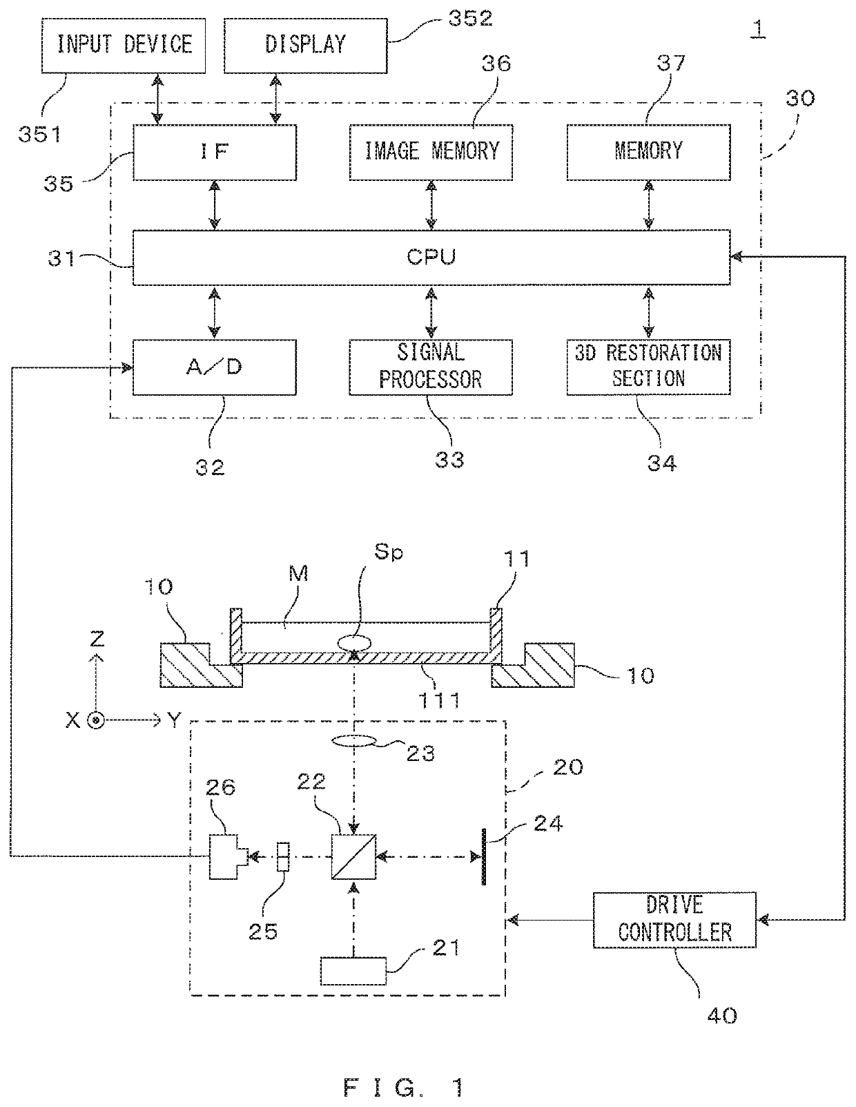
[0034]FIG. 1 is a drawing showing a configuration example of an image processing apparatus on which the present invention is applied. The image processing apparatus 1 tomographically images a spheroid (cell aggregate) cultured in culture medium as an imaging object, processes the obtained image and generates a stereoscopic image of the spheroid. Note that although an example of imaging a spheroid as the imaging object is illustrated here, the imaging object is not limited to this. For unified presentation of the directions in drawings, the XYZ orthogonal coordinate axes are established as shown in FIG. 1. The XY plane is a horizontal surface. The Z axis represents the vertical axis, in more detail, the (−Z) direction represents the vertically downward direction.

[0035]The image processing apparatus 1 comprises a holder 10. The holder 10 holds in an approximately horizontal posture a container 11 in such a manner that its opening is directed toward above. The container 11 has a flat b...


PUM

PropertyMeasurementUnit
optically transparentaaaaaaaaaa
optical path lengthaaaaaaaaaa
thicknessaaaaaaaaaa

Abstract

The present invention aims to obtain a tomographic image free from image noise due to reflection on a container wall surface and having a good image quality by a simple configuration. In a FD-OCT imaging apparatus which images an imaging object stored in a container having an optical transparent wall part tomographically, when the focal depth is set such that a distance D from a first surface Sa of the wall part on the side of the imaging object to a focal point FP of the objective optical system is smaller than a predetermined threshold value smaller than a thickness T of the wall part, the distance between a second surface Sb of the wall part on a side opposite to the imaging object out of the wall surfaces and a reference plane which is perpendicular to the optical path of the illumination light and to which an optical path length is equal is set a value equal to the thickness of the wall part.

Description

TECHNICAL FIELD[0001]This invention relates to a technique for imaging by detecting an interference light component of reflected light from an imaging object and reference light and particularly to a technique for imaging an imaging object carried in a carrier having optical transparency.BACKGROUND ART[0002]In technical fields of medicine and biochemistry, samples carried in an appropriate carrier such as cells and microorganisms cultured in a container are observed. Techniques for imaging cells and the like using a microscope or the like are proposed as methods for observation without affecting the cells and the like to be observed. One of such techniques utilizes an optical coherence tomography technique. In this technique, low-coherence light emitted from a light source is caused to be incident as illumination light on an imaging object and interference light of reflected light (signal light) from the imaging object and reference light having a known optical path length is detect...

Claims


Application Information

Patent Timeline
Patent Type & Authority Applications(United States)
IPC IPC(8): G01B9/02G01N21/55
CPCG01B9/02084G01N21/55G01B9/02091G01N21/4795G01N2021/1787G01B9/02064G01B9/02044G01B9/02078
Inventor KATO, KEISUKEISHIKAWA, NAOKI
Owner DAINIPPON SCREEN MTG CO LTD
Why Eureka
Try Eureka