Connection method, connection tool, and connection jig for optical fiber

a technology of optical fiber and connection jig, which is applied in the direction of manufacturing tools, instruments, other domestic articles, etc., can solve the problems of difficult operation of adjusting the bevel direction, and achieve the effect of accurate alignment of the bevel direction, low loss, and reduced reflections at the connection par

Active Publication Date: 2011-04-07
THE FUJIKURA CABLE WORKS LTD
View PDF11 Cites 13 Cited by
  • Summary
  • Abstract
  • Description
  • Claims
  • Application Information

AI Technical Summary

Benefits of technology

[0037]According to the embodiments of the present invention, it is possible to accurately align the bevel direction of the front end face of the second optical fiber (the other optical fiber), which is beveled, with the bevel direction of the front end face of the first optical fiber (one optical fiber), which is fixed in the optical connector. As a result, it is possible to reduce the reflections at the connection part, so that a connection with low loss can be realized.
[0038]Furthermore, at the time of the connection operation, it is easy to confirm the bevel direction of the front end face of the second optical fiber, and also it is not necessary to perform the adjustments for the bevel direction, so that manipulation is easy.
[0039]Therefore, the operation for assembling the optical connector at the front end of the second optical fiber in the field is simplified. Moreover, it is possible to connect optical fibers with different thicknesses without changing the structure of the optical connector.

Problems solved by technology

However, there is a problem in that the operation of adjusting these bevel directions is difficult.

Method used


Image

  • Connection method, connection tool, and connection jig for optical fiber
  • Connection method, connection tool, and connection jig for optical fiber
  • Connection method, connection tool, and connection jig for optical fiber

Examples


first embodiment

[0119]Hereunder is a description of the present invention with reference to the drawings.

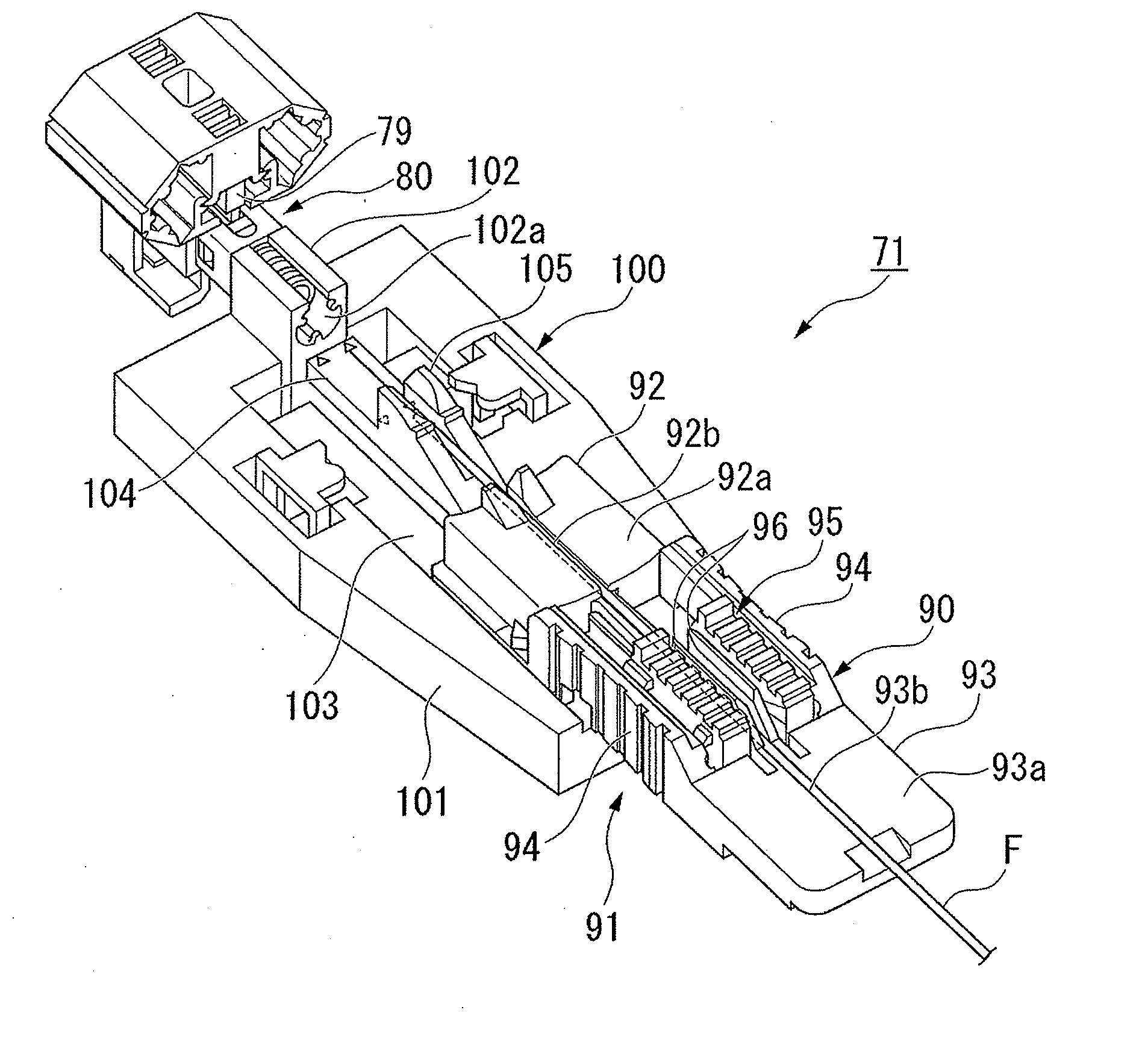
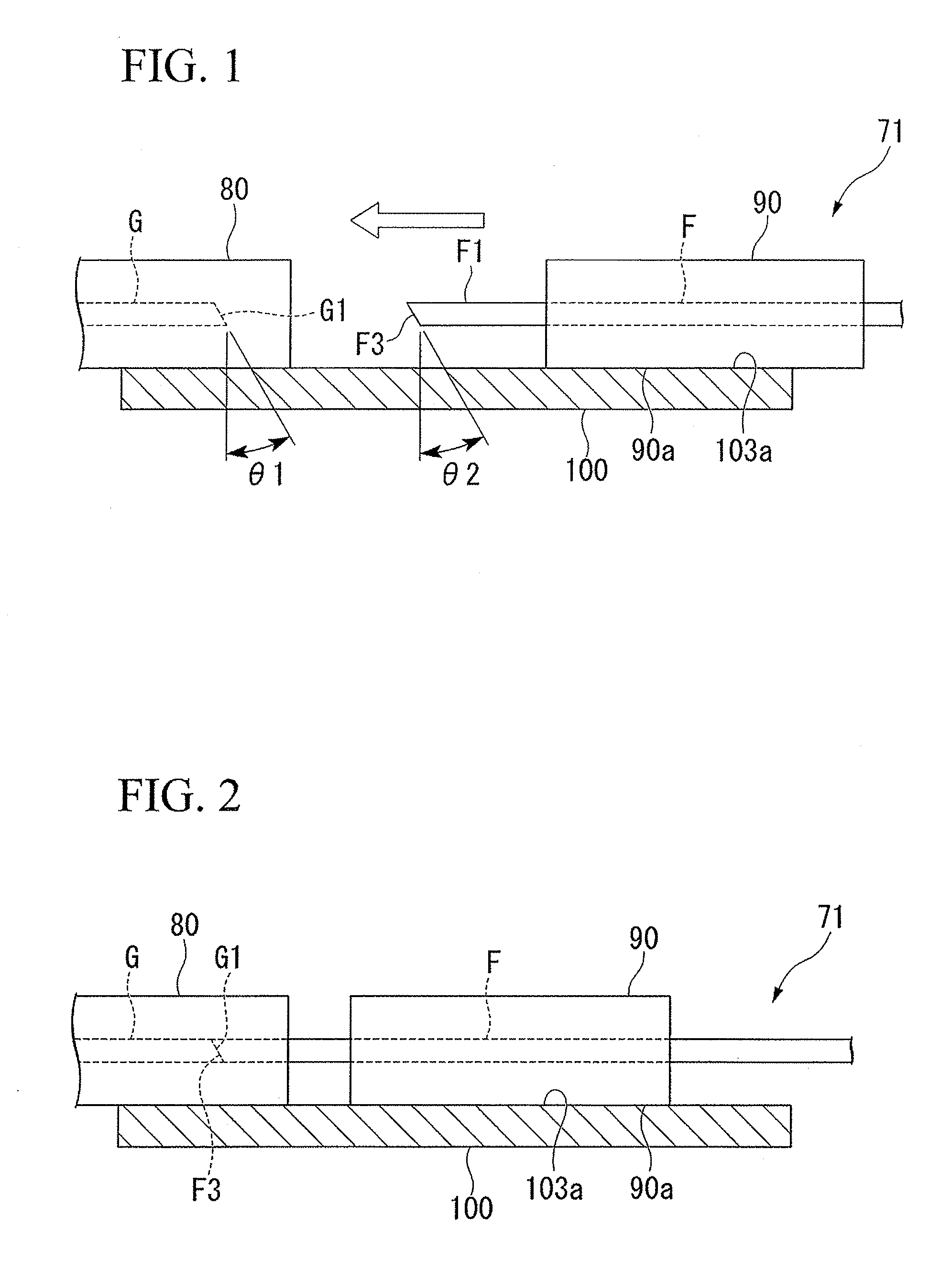
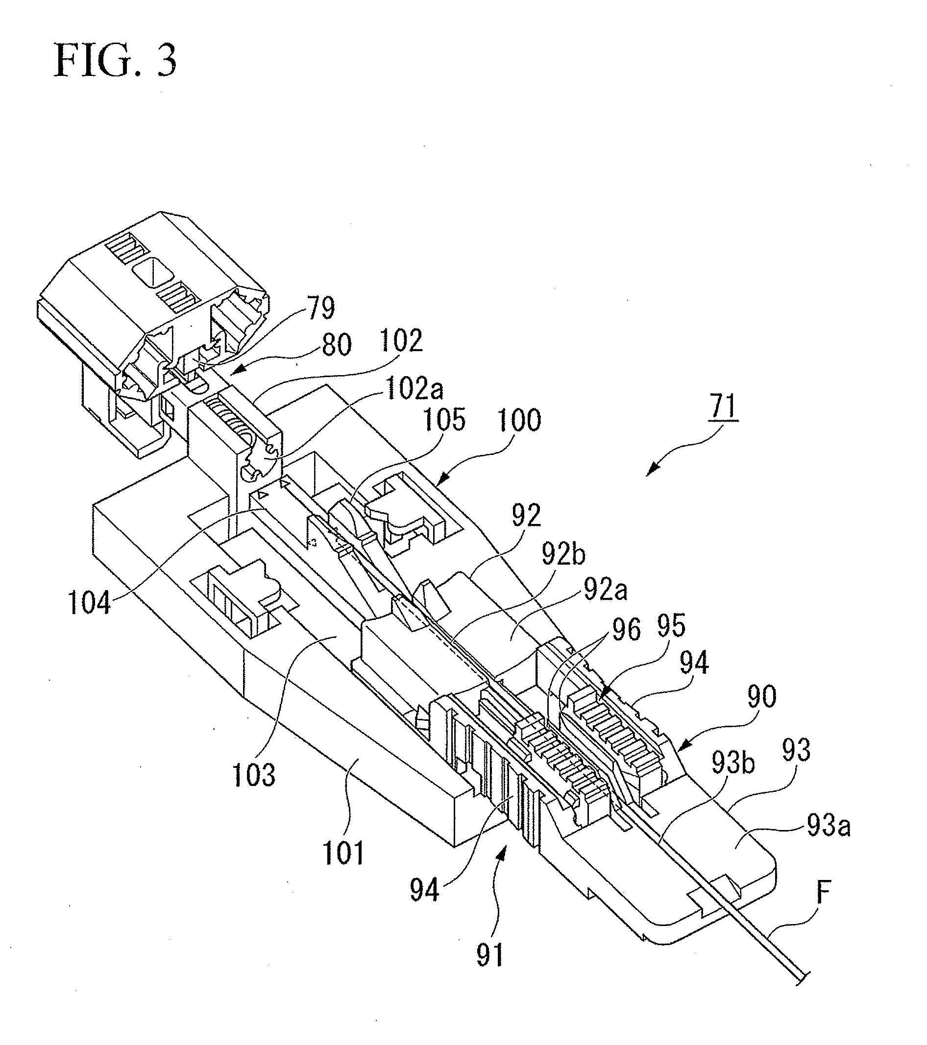
[0120]FIG. 1 and FIG. 2 are schematic structural views showing an optical fiber connection tool 71, which is an example of an optical fiber connection tool of the present invention. FIG. 3 and FIG. 4 are perspective views showing the optical fiber connection tool 71. FIG. 5 is a perspective view showing an optical fiber holder 90 of the optical fiber connection tool 71. FIG. 6 is a perspective view showing a holder support base 100 of the optical fiber connection tool 71. FIG. 7 is an exploded perspective view of the main parts of an optical connector 80 that is used for an example of an optical fiber connection method of the present invention. FIG. 8 is a perspective view showing a clamp part. FIG. 9A is an exploded side view showing the clamp part.FIG. 9B is a horizontal direction cross-sectional view showing the clamp part.

[0121]As shown in FIG. 1, the optical fiber connection tool 71 is one ...


PUM

PropertyMeasurementUnit
bevel angleaaaaaaaaaa
outer diameteraaaaaaaaaa

Abstract

A method of butting and connecting a first optical fiber and a second optical fiber in an optical connector comprises placing said optical connector that holds said first optical fiber in wherein an optical fiber connection tool; mounting said optical fiber holder on a holder mounting base of a front end bevel processing tool; processing a front end face of said second optical fiber such that said front end face of said second optical fiber is beveled relative to the surface perpendicular to the optical fiber axis direction; transferring said optical fiber holder to said holder support base; and moving said optical fiber holder toward said optical connector along said guide part, and butting and connecting the beveled front end face of said second optical fiber to the front end face of said first optical fiber such that their bevel directions are aligned.

Description

CROSS-REFERENCE TO RELATED APPLICATION[0001]This is a Continuation Application of International Application No. PCT / JP2009 / 060612, filed on Jun. 10, 2009, which claims priorities to Japanese Patent Application No. 2008-155993, filed Jun. 13, 2008, and Japanese Patent Application No. 2008-156024, filed Jun. 13, 2008. The contents of the aforementioned applications are incorporated herein by reference.TECHNICAL FIELD[0002]The present invention relates to a connection method, a connection tool, and a connection jig used therefore, in which the connection method is used for butting and connecting a pair of optical fibers to each other in a field assembly type optical connector or an optical connector comprising a mechanical splicing unit.BACKGROUND ART[0003]In an optical fiber connection, for example, in a field assembly type optical connector with a built in mechanical splice, or in a mechanical splicing unit, a method is used in which end part of a first optical fiber is butted and co...

Claims


Application Information

Patent Timeline
Patent Type & Authority Applications(United States)
IPC IPC(8): G02B6/26G02B6/46
CPCG02B6/262G02B6/3898G02B6/3862G02B6/3846
Inventor SAITO, DAIGOTAKIZAWA, KAZUHIROFURUKAWA, HIROSHITAN, SERIN KHEE YENNGO, QUANG MINH
Owner THE FUJIKURA CABLE WORKS LTD
Why Eureka
Try Eureka