Switch Driving Circuit And Driving Method Thereof

Active Publication Date: 2011-04-07
SEMICON COMPONENTS IND LLC
View PDF7 Cites 69 Cited by
  • Summary
  • Abstract
  • Description
  • Claims
  • Application Information

AI Technical Summary

Benefits of technology

[0022]As described above, the switch driving device and a driving method according to the present

Problems solved by technology

Then, the entire power control system includ

Method used


Image

  • Switch Driving Circuit And Driving Method Thereof
  • Switch Driving Circuit And Driving Method Thereof
  • Switch Driving Circuit And Driving Method Thereof

Examples


Example

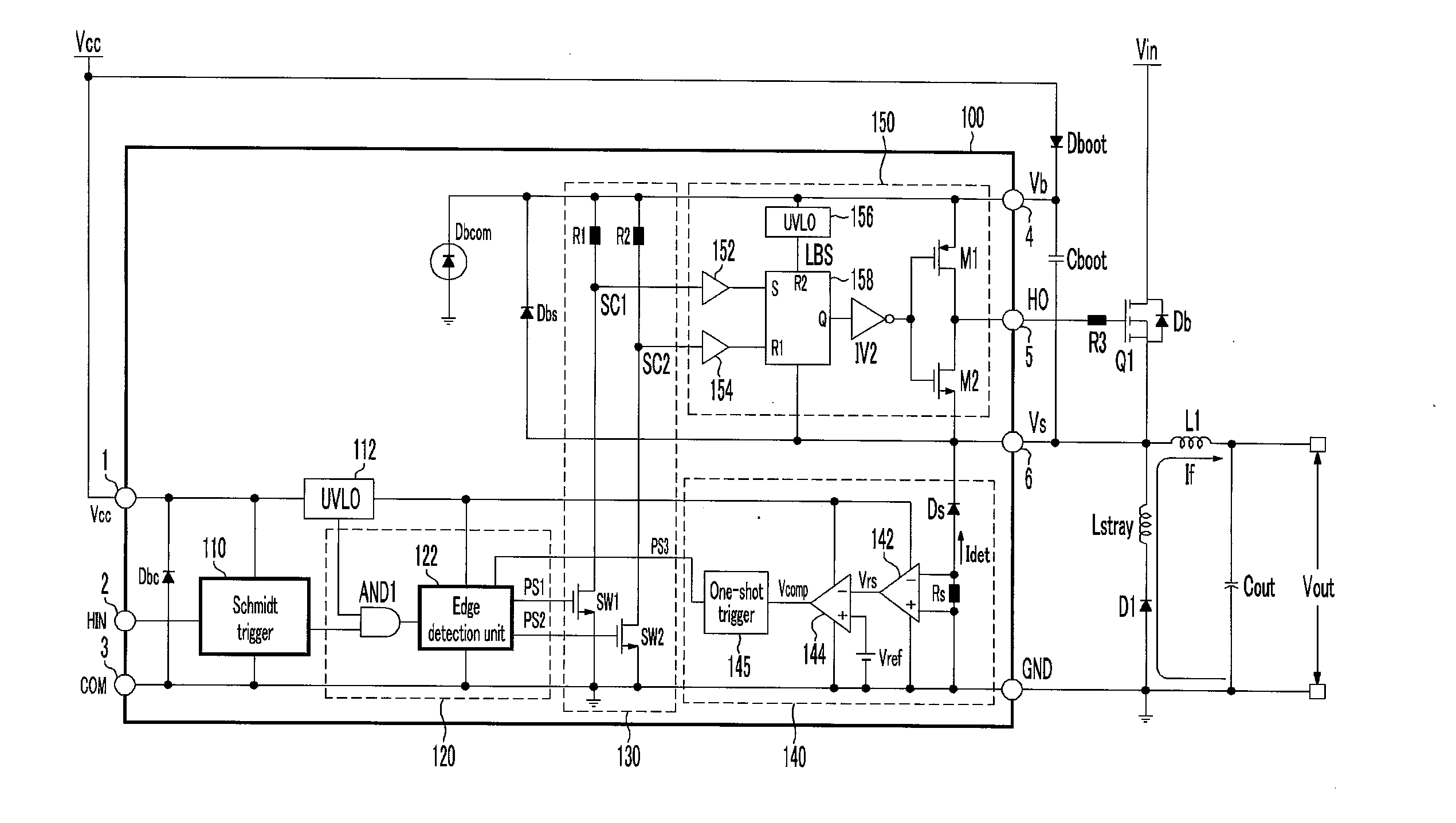
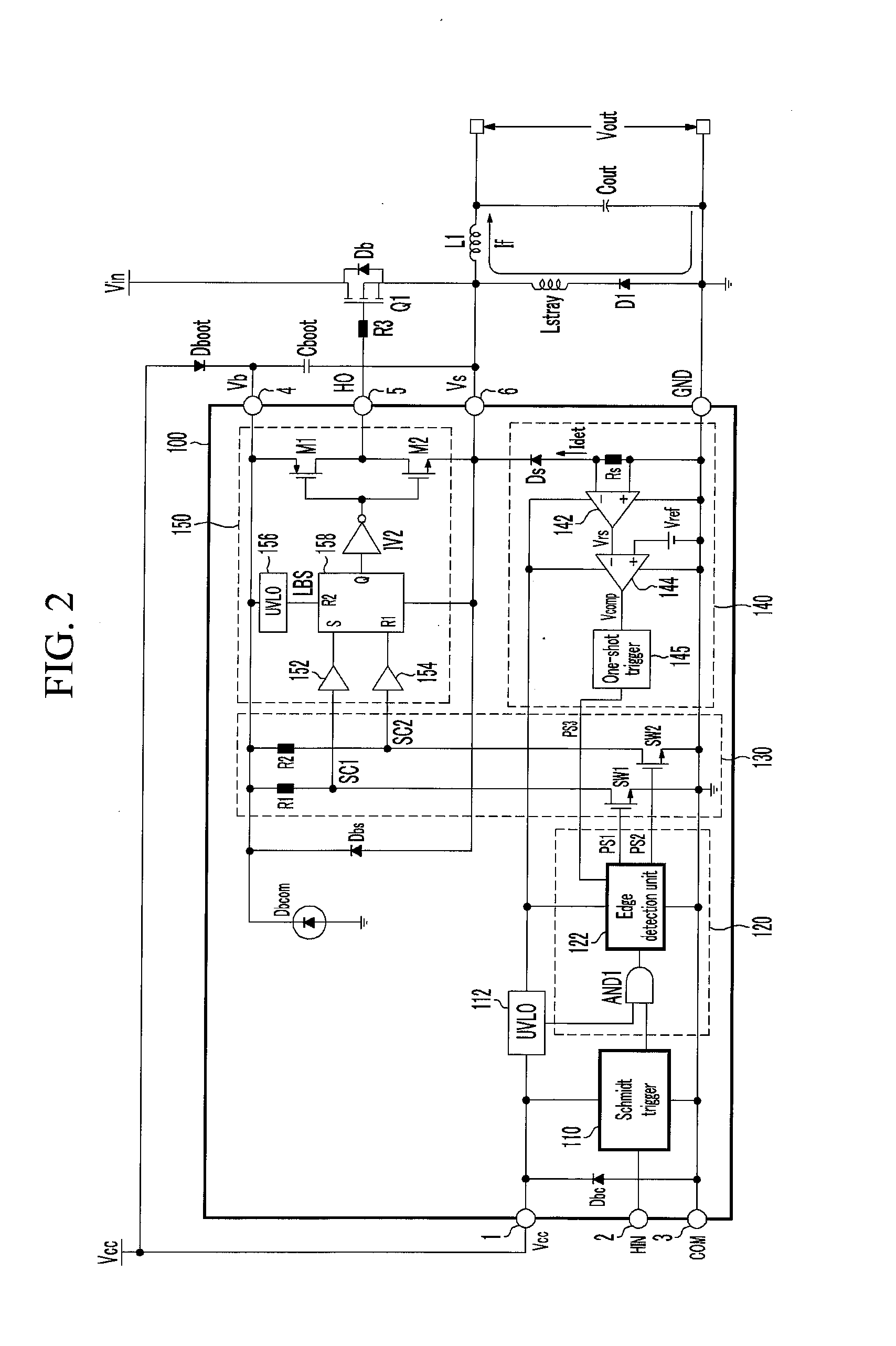
[0093]FIG. 6 shows a switch driving circuit according to the third exemplary embodiment of the present invention.

[0094]A protection unit 140″ further includes a one-shot trigger 145′ compared to the protection unit 140′ of the second exemplary embodiment, and an edge detection unit 122′ generates an OFF control signal PS2 according to a protection pulse signal PS3′ output from the one-shot trigger 145′. In further detail, the edge detection unit 122″ is synchronized at a rising time of the protection pulse signal PS3′ and generates the OFF-pulse signal PS2.

[0095]In the exemplary embodiments of the present invention, the edge detection unit 122 detects the rising time of the negative voltage protection signal NPS or the protection pulse signals PS3 and PS3′, but it may generate an OFF pulse signal PS2 by detecting a falling time of the negative voltage protection signal NPS or the protection pulse signals PS3 and PS3′ when their waveforms are changed. That is, the edge detection unit...


PUM


Abstract

The present invention relates to a switch driving circuit and a driving method thereof.
The switch driving circuit according to the present invention is supplied with a first voltage and a second voltage, is driven by a voltage difference between the first and second voltages, controls a switching operation of a power switch according to a switch driving control signal, generates a sense voltage corresponding to the second voltage, compares a predetermined reference voltage with the sense voltage, and stops the switching operation of the power switch according to the comparison result.

Description

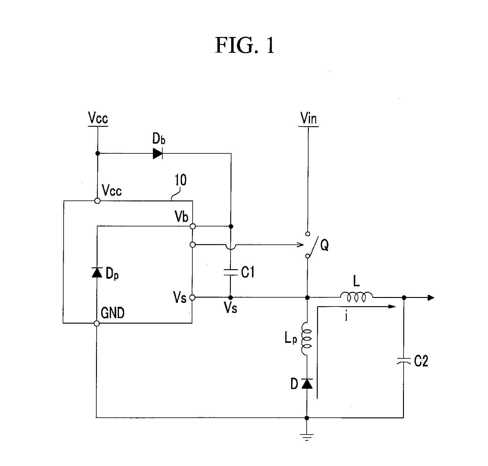
CROSS-REFERENCE TO RELATED APPLICATION[0001]This application claims priority to and the benefit of Korean Patent Application No. 10-2009-0094780 filed in the Korean Intellectual Property Office on Oct. 6, 2009, the entire contents of which are incorporated herein by reference.BACKGROUND OF THE INVENTION[0002](a) Field of the Invention[0003]The present invention relates to a switch driving circuit and a driving method thereof, and particularly relates to a switch driving circuit that can prevent a malfunction due to a negative voltage generated therein and a driving method thereof.[0004](b) Description of the Related Art[0005]FIG. 1 schematically shows a conventional switch driving circuit. Referring to FIG. 1, a switch driving circuit 10 is connected to both ends of a bootstrap capacitor C1 and is driven by a voltage charged therein. A bootstrap diode Db is connected between a power source Vcc and the bootstrap capacitor C1, and is turned on during a period during which a source vol...

Claims


Application Information

Patent Timeline
IPC IPC(8): H03K17/16
CPCH03K17/165H03K17/0822
Inventor LEE, YOUNG SIK
Owner SEMICON COMPONENTS IND LLC
Why Eureka
Try Eureka