Boundary acoustic wave device

Active Publication Date: 2011-04-07
MURATA MFG CO LTD
View PDF3 Cites 13 Cited by
  • Summary
  • Abstract
  • Description
  • Claims
  • Application Information

AI Technical Summary

Benefits of technology

[0014]To overcome the problems described above, preferred embodiments of the present invention provide a boundary acoustic wave device including a ladder circuit configuration which increases the attenuation outside of a passband and advantageously enables a reduction in size.

Problems solved by technology

The attenuation in a band lower than a passband can be increased while maintaining the width of the passband, by making the inductance component Lp extremely small and selecting an appropriate value for the inductance component L. However, in actual surface acoustic wave devices, it is very difficult to make the value of the inductance component Lp small due to restrictions on wiring of lines and other circuit limitations.
Consequently, the method of increasing the attenuation outside of a passband by using the inductance component L and the capacitor 1010 described in Japanese Unexamined Patent Application Publication No. 2003-101384 is not effective for a boundary acoustic wave device.

Method used


Image

  • Boundary acoustic wave device
  • Boundary acoustic wave device
  • Boundary acoustic wave device

Examples


Embodiment Construction

[0041]Hereinafter, specific preferred embodiments of the present invention are described with reference to the drawings, thereby clarifying the invention.

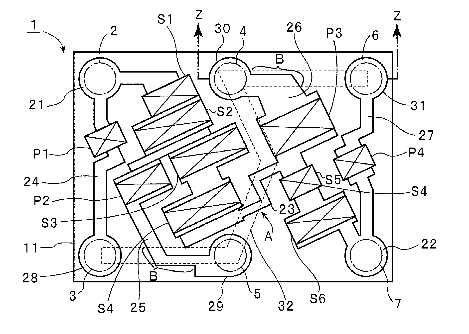
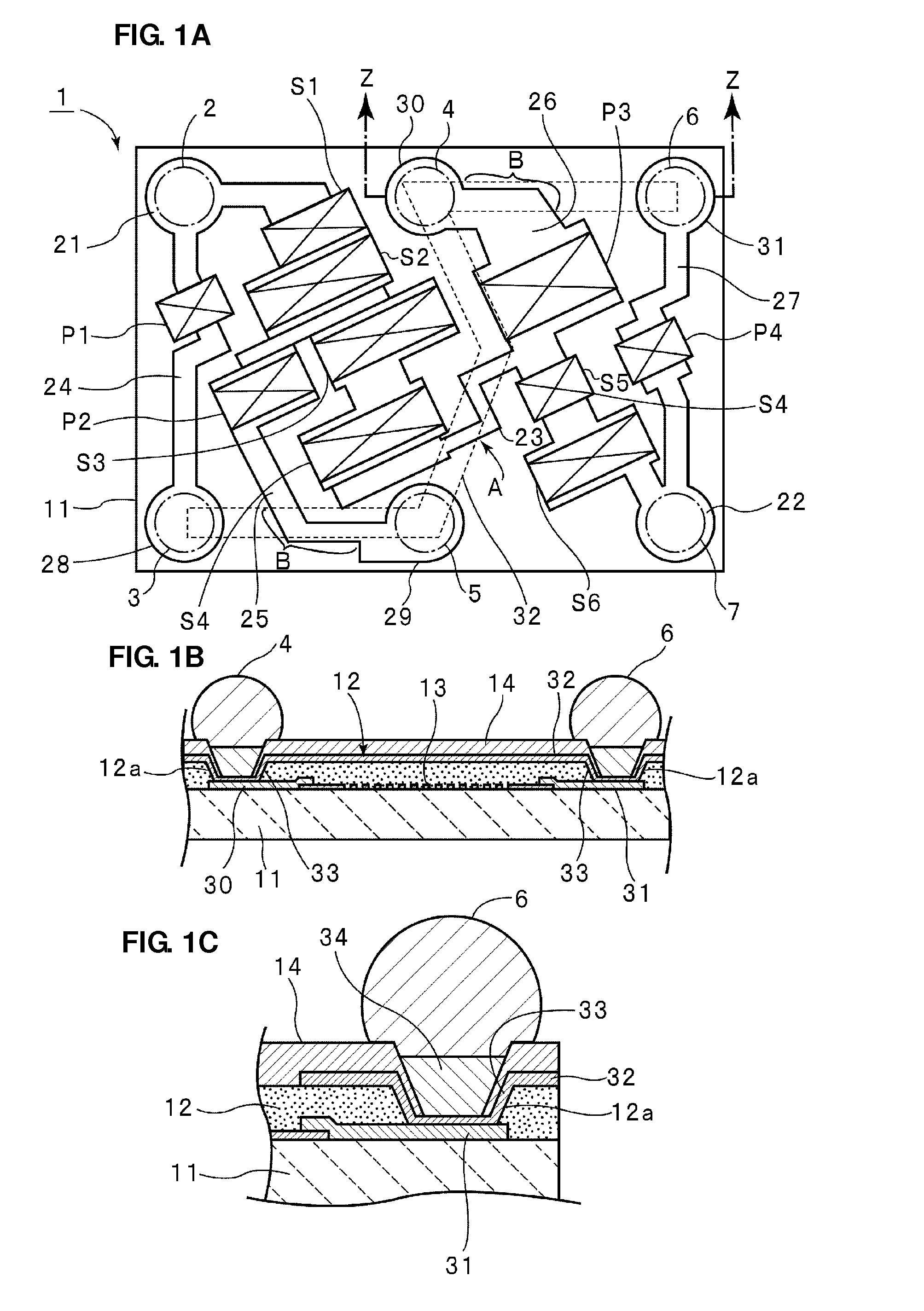
[0042]FIG. 1A is an explanatory schematic plan view of the main portions of a boundary acoustic wave filter device according to a first preferred embodiment of the present invention, FIG. 1B is a simplified partial front sectional view of the boundary acoustic wave device, and FIG. 1C is a partially cut off and magnified front sectional view of the main portions shown in FIG. 1B.

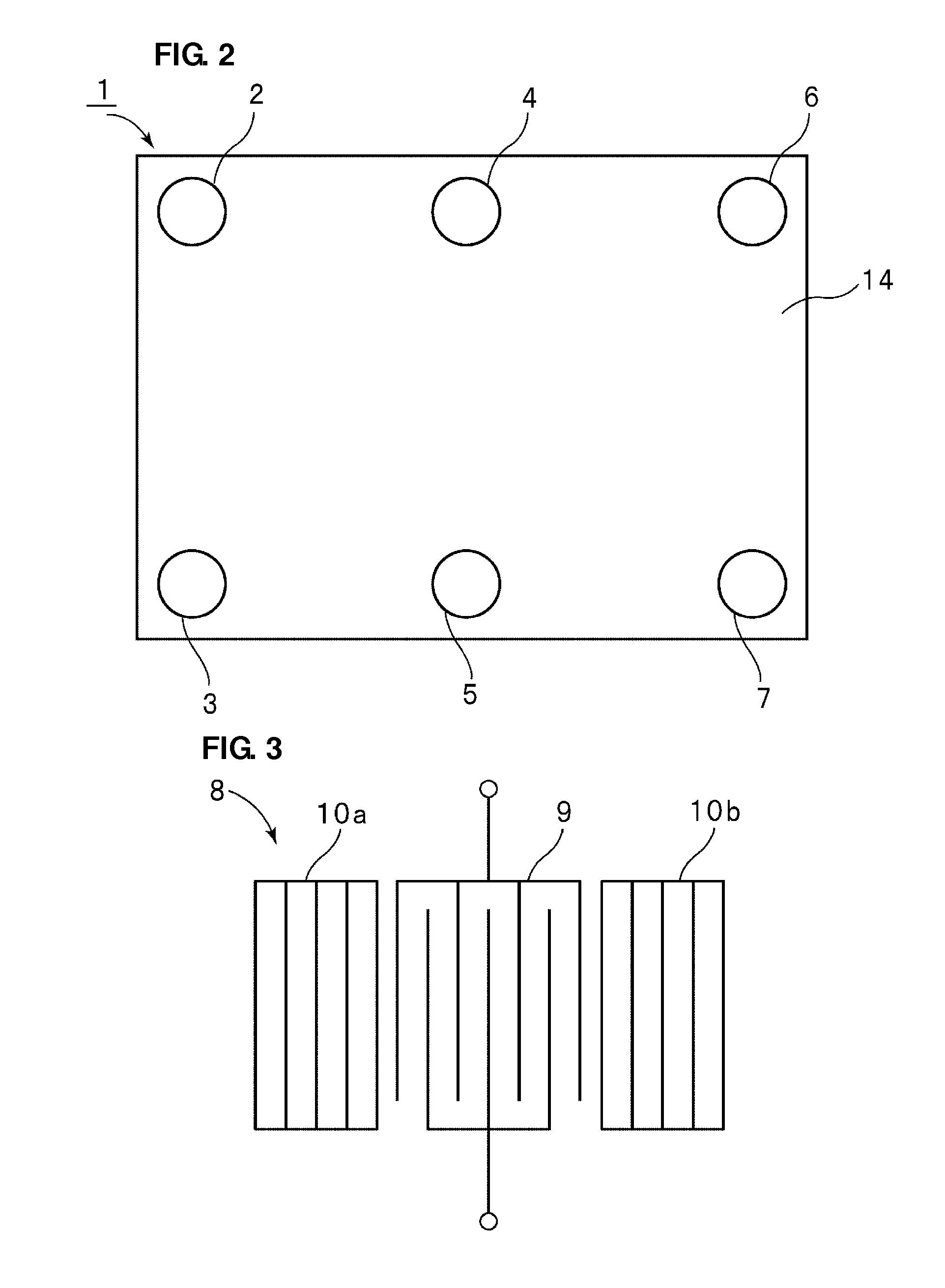
[0043]FIG. 2 is a plan view of a boundary acoustic wave device according to the first preferred embodiment of the present invention.

[0044]Referring to FIG. 2, the boundary acoustic wave device 1 preferably has a substantially planar rectangular shape, for example. The boundary acoustic wave device 1 includes metal bumps 2 to 7 arranged on the upper surface thereof. By utilizing the metal bumps 2 to 7, the boundary acoustic wave device 1 can be surface-mount...


PUM


Abstract

A boundary acoustic wave device includes an electrode structure that is provided at the interface between a piezoelectric substrate and a dielectric layer. The electrode structure defines a ladder filter in which at least two ground pads of a plurality of ground pads, to be connected to a ground potential, provided on the piezoelectric substrate are electrically connected by a connection conductor provided on the dielectric layer, and all of the ground pads are electrically connected.

Description

BACKGROUND OF THE INVENTION[0001]1. Field of the Invention[0002]The present invention relates to a boundary acoustic wave device including an electrode structure arranged at the interface between a piezoelectric substrate and a dielectric layer, and more specifically, to a boundary acoustic wave filter including a ladder circuit configuration.[0003]2. Description of the Related Art[0004]It is required that a band pass filter used in cellular phones have a large amount of attenuation in bands outside of a passband. In the past, a surface acoustic wave filter device has widely been used as such a band pass filter.[0005]FIG. 10 is a circuit diagram showing a surface acoustic wave filter device disclosed in Japanese Unexamined Patent Application Publication No. 2003-101384. The surface acoustic wave filter device 1001 includes a series arm that connects an input terminal 1002 and an output terminal 1003. On the series arm, series arm resonators 1004 to 1006 are connected in series. A pl...

Claims


Application Information

Patent Timeline
IPC IPC(8): H03H9/02
CPCH03H9/059H03H9/1071H03H9/6493H03H9/6483H03H9/14538H01L2224/11
Inventor HARUTA, KAZUMASA
Owner MURATA MFG CO LTD
Why Eureka
Try Eureka