power converter

a power converter and converter technology, applied in the field of power converters, can solve the problems of not being able to synchronize across a number of power converter stages, known types of construction, and inability to achieve frequency smearing in converters

Active Publication Date: 2011-04-07
TEXAS INSTR INC
View PDF28 Cites 13 Cited by
  • Summary
  • Abstract
  • Description
  • Claims
  • Application Information

AI Technical Summary

Benefits of technology

[0025]In one embodiment of the present invention there is provided a method further comprising the step of continuously g...

Problems solved by technology

There are however problems with the known types of constructions.
By and large, these converters do not permit synchronisation to an accurate signal such as a reference signal from another stage of the power converter, and therefore s...

Method used


Image

  •  power converter
  •  power converter
  •  power converter

Examples


Embodiment Construction

[0032]The invention will now be more clearly understood from the following description of some embodiments thereof given by way of example only with reference to and as illustrated by the accompanying drawings in which:—

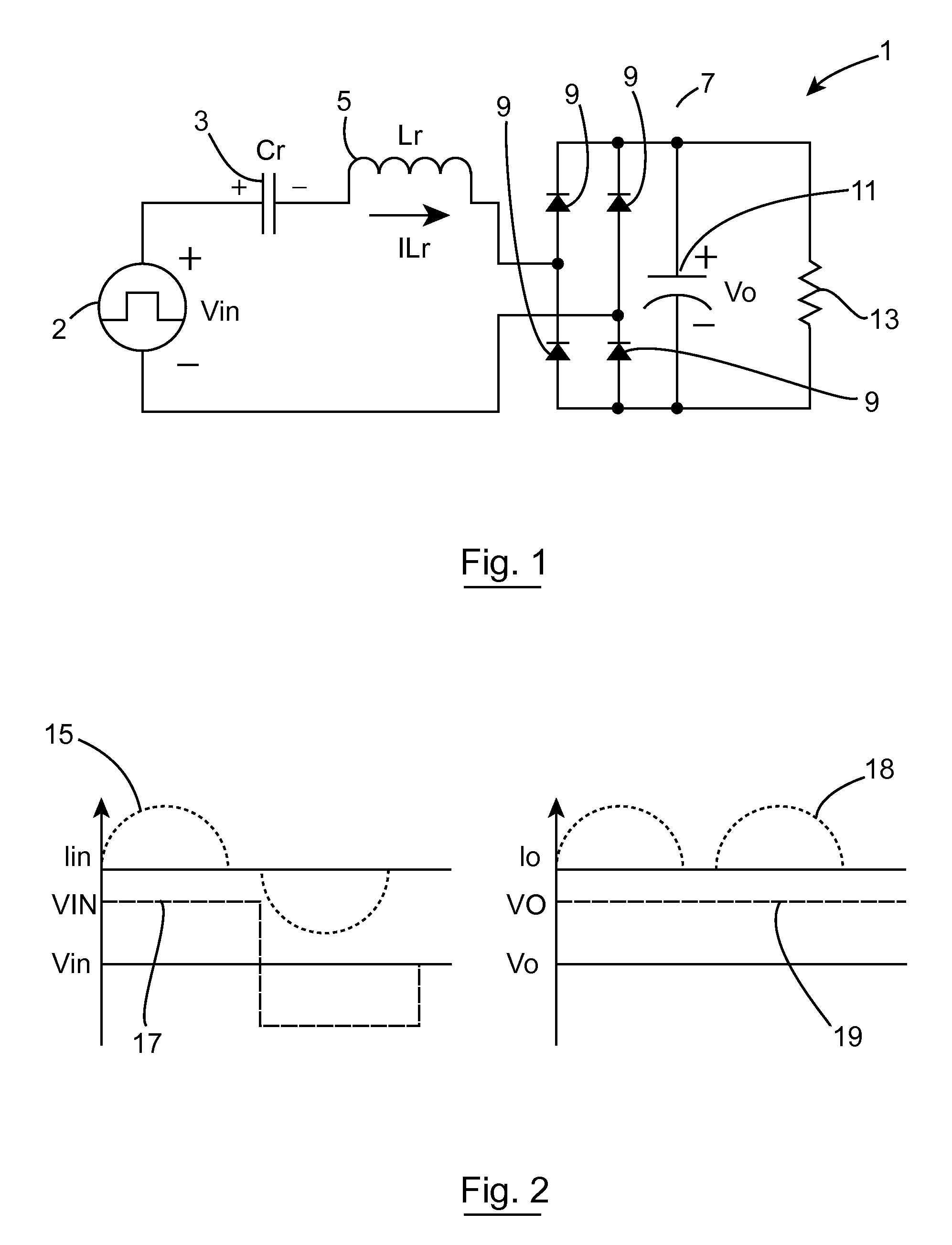
[0033]FIG. 1 is a circuit schematic of a resonant mode power converter known in the art;

[0034]FIG. 2 shows wave diagrams relating to the circuit shown in FIG. 1;

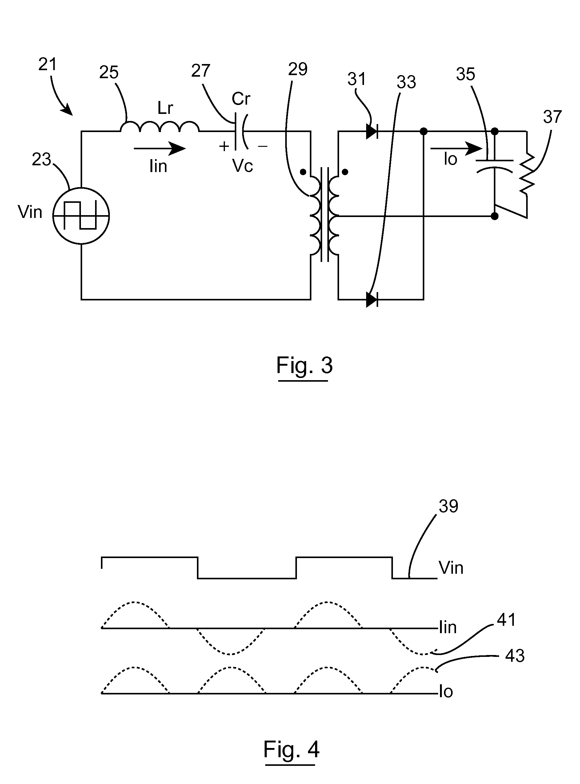
[0035]FIG. 3 is a circuit schematic of another resonant mode power converter known in the art;

[0036]FIG. 4 shows wave diagrams relating to the circuit shown in FIG. 3;

[0037]FIG. 5 is a circuit schematic representation of a gate drive scheme for secondary power switches for use in conjunction with an LLC resonant converter according to the invention;

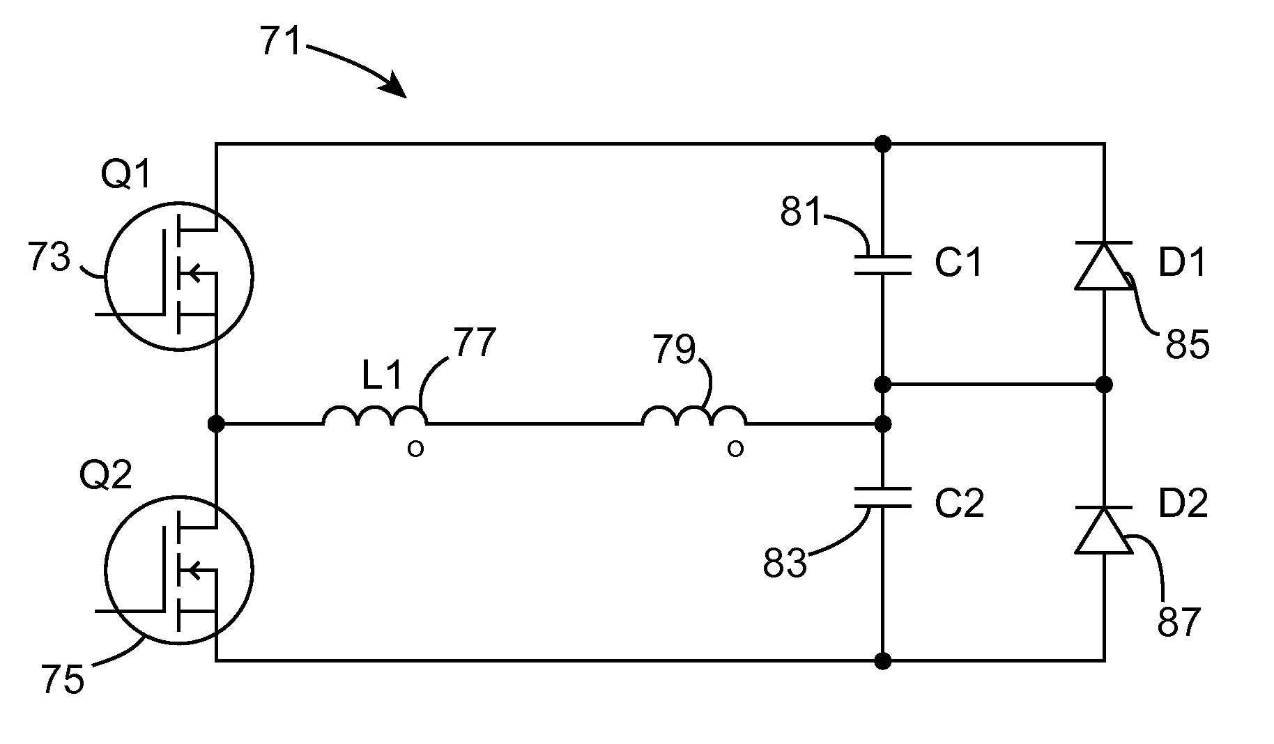
[0038]FIG. 6 is a circuit schematic representation of a half bridge implementation of series resonant converter according to the invention;

[0039]FIG. 7 is a circuit schematic representation of a power converter with a half bridge implementation of series resonant c...


PUM


Abstract

The present invention relates to a power converter (90) and a method of operating same. There are numerous advantages to operating power converters using a series resonant converter (1, 21). This approach is particularly suitable for minimising switching losses in the power converter when it is operated at high frequency. However, there are problems with the known converters in that they are prone to generate noise in the acoustic spectrum due to the fact that the converter stages are often operating at different frequencies. The present invention relates to a power converter and a method of operating same that enables the operating frequency of the converter to be controlled by a control circuit over a predetermined range of the resonant frequency. This allows reduction in acoustic noise generation and facilitates frequency smearing that will in turn reduce spectral peaks. This is achieved whilst maintaining output ripple within acceptable ranges.

Description

INTRODUCTION[0001]This invention relates to a power converter and in particular to a power converter operating using resonant mode power conversion. The invention further relates to a method of operating such a power converter.[0002]It is generally well known that resonant-type power conversion can improve the efficiency of a power converter. Two known approaches that are particularly appropriate are resonant converters that can achieve zero-current switching (“ZCS”) and zero-voltage switching (“ZVS”). Such converters can operate with zero power-train switching losses. This is highly desirable. A further level of loss reduction may be achieved by using resonant gate drives, and more specifically, resonant transition types. These allow the gate driving power requirement to be reduced significantly, thus contributing further to loss reduction.[0003]Heretofore, various constructions of resonant converters have been proposed that are suited to achieving such performance. It is understoo...

Claims


Application Information

Patent Timeline
IPC IPC(8): H02M3/335
CPCH02M3/3376H02M3/33592Y02B70/1433Y02B70/1475Y02B70/10
Inventor YOUNG, GEORGE
Owner TEXAS INSTR INC
Why Eureka
Try Eureka