Ratcheting tensioner with a sliding and pivoting pawl

a technology of ratcheting tensioner and pivoting pawl, which is applied in the direction of belt/chain/gearing, mechanical equipment, belts, etc., can solve the problems of chain control loss or other undesirable effects

Inactive Publication Date: 2011-04-07
BORGWARNER INC
View PDF26 Cites 27 Cited by
  • Summary
  • Abstract
  • Description
  • Claims
  • Application Information

AI Technical Summary

Benefits of technology

[0015]Ejection of the piston from the bore of the housing is prevented when the pawl rotates, such that the first protruding shoulder contacts the housing and the teeth portion closest to the second shoulder engage a shoulder in a stop groove on the outer circumference of the piston.

Problems solved by technology

When chain load spikes or a loss of fluid pressure is present, retraction of the plunger occurs and if the retraction of the plunger is excessive, loss of chain control or other undesirable effects occur.
One of the problems with the tensioner of U.S. Pat. No. 4,874,352 is that the piston 3 rotates and ratchets with the rack 13 along the outer circumference of the piston 3 up until all of the teeth on the pawl 12 no longer mesh with piston's rack 13.

Method used


Image

  • Ratcheting tensioner with a sliding and pivoting pawl
  • Ratcheting tensioner with a sliding and pivoting pawl
  • Ratcheting tensioner with a sliding and pivoting pawl

Examples


Embodiment Construction

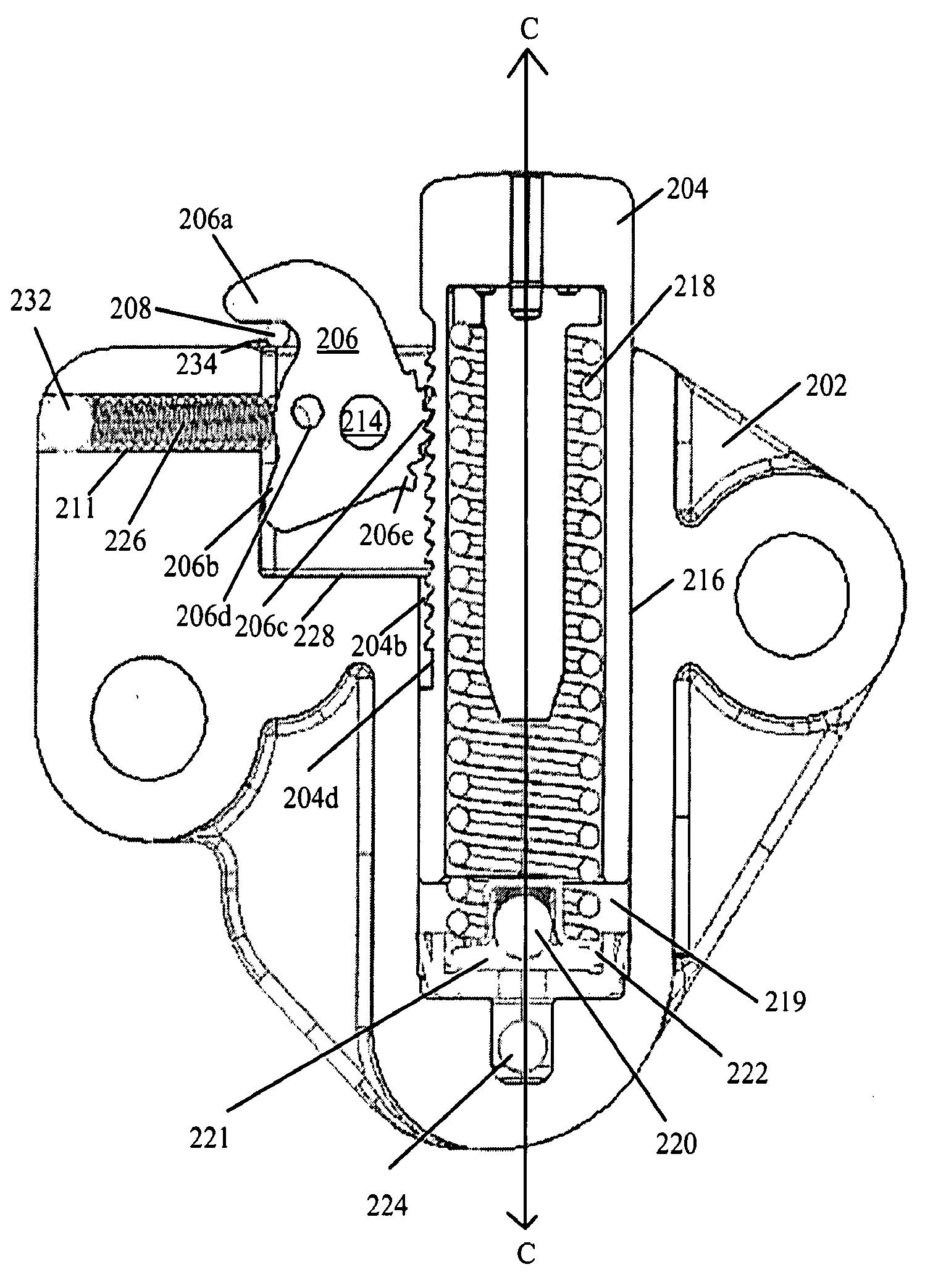
[0032]FIGS. 5 through 13 show the tensioner of the present invention. The tensioner includes a housing 202 having a cutout 228 for receiving a rotating, sliding pawl 206 and a bore 216 for slidably receiving a hollow piston 204 that creates a fluid chamber 219 with the bore 216. A passage 224 in the housing 202 connects the fluid chamber 219 with a pressurized source of fluid. A check valve 221 comprising a check ball 220 and a seat 222, allows fluid into the fluid chamber 219 only. The piston 204 is biased by a piston spring 218 in a protruding direction from the housing 202 toward a chain or belt (not shown). The piston 204 contains a series of grooves 204b around or across, at least a portion of the outer circumference of the piston 204 for ratcheting with the rotating, sliding pawl 206. At least one of the grooves acts as a stop 204d, to help prevent the ejection of the piston 204 from the housing 202.

[0033]The rotating, sliding pawl 206 is rotatably attached to the housing by a...


PUM


Abstract

A tensioner with a piston is slidably received with a bore (216) of the housing and has a plurality of grooves (204b) formed on its outer circumference. A piston spring (226) biases the piston (204) in an outward direction from the bore. A pawl (206) is received by a cutout in the housing and is pivotally and slidably attached to the housing by a pin (208). The pawl has a first protruding shoulder (206a), a second shoulder (206b), a teeth portion (206c), and a hole (211) defined between the first protruding shoulder and the second shoulder. The pawl is biased toward the grooves formed on the outer circumference of the piston by a spring.

Description

REFERENCE TO RELATED APPLICATIONS[0001]This application claims one or more inventions which were disclosed in Provisional Application Ser. No. 60 / 746,659, filed May 8, 2006, entitled “RATCHETING TENSIONER WITH A SLIDING AND PIVOTING PAWL”. The benefit under 35 USC §119(e) of the United States provisional application is hereby claimed, and the aforementioned application is hereby incorporated herein by reference.BACKGROUND OF THE INVENTION[0002]1. Field of the Invention[0003]The invention pertains to the field of tensioners. More particularly, the invention pertains to tensioners with a sliding and pivoting pawl.[0004]2. Description of Related Art[0005]In chain and belt tensioners, pistons are urged from their housings by a spring or a spring plus hydraulic pressure. Check valves are added to tensioners between the pressurized fluid source and the fluid chamber formed between the housing and the piston to prevent backflow of the hydraulic fluid out of the fluid chamber. The rate of l...

Claims


Application Information

Patent Timeline
Patent Type & Authority Applications(United States)
IPC IPC(8): F16H7/08
CPCF16H7/0848F16H2007/0853F16H2007/0806F16H7/08
Inventor MARKELY, GEORGE L.
Owner BORGWARNER INC
Why Eureka
Try Eureka