Surface texture measuring machine and a surface texture measuring method

a measuring machine and surface texture technology, applied in the direction of mechanical roughness/irregularity measurement, measurement devices, instruments, etc., can solve the problems of measurement results that may also have errors, measurement results that may have errors, measurement results that may not be accurate, etc., to reduce the burden on the operator and prevent interferen

Active Publication Date: 2011-04-14
MITUTOYO CORP
View PDF9 Cites 21 Cited by
  • Summary
  • Abstract
  • Description
  • Claims
  • Application Information

AI Technical Summary

Benefits of technology

[0041]When the probe head is oriented in the displacing direction of the stylus, for instance, an image of the object from a horizontal surface can be captured. When the probe head is oriented in the direction perpendicular to the displacing direction of the stylus, an image of the object from a vertical surface can be captured. Accordingly, even at a measurement of an inner surface texture of a hole formed on the vertical surface, by capturing the image of the vertical surface of the object by using the image probe, the stylus can be accurately positioned inside the hole formed on the vertical surface. Therefore, the stylus can be prevented from interfering with the object while reducing the burden on the operator.

Problems solved by technology

Moreover, in the surface texture measuring machine, when an attitude of the object is inclined relative to a measurement axis in measuring a surface of the object, a measurement result may have an error.
For this reason, a measurement value includes a value showing an outer circumferential texture of the cylinder as well as a value showing an axial concavity and convexity of the surface of the cylinder, so that the measurement result has an error.
Moreover, in the surface texture measuring machine, when a to-be-measured surface is inclined relative to a horizontal plane, the measurement result may also have an error.
Accordingly, the above setting operation of a stylus, which is quite complicated and requires a long time, places a large burden on the operator.
In addition, some types of objects may interfere with (collide with) a stylus to damage the stylus or the objects.
Moreover, in the surface texture measuring machine of Patent Literature 2, it takes extremely long time for the preliminary measurement because the preliminary measurement requires many steps and uses the stylus for measuring the surface of the object.
Further, the object may be damaged by the stylus.

Method used


Image

  • Surface texture measuring machine and a surface texture measuring method
  • Surface texture measuring machine and a surface texture measuring method
  • Surface texture measuring machine and a surface texture measuring method

Examples


first exemplary embodiment

Advantages of First Exemplary Embodiment

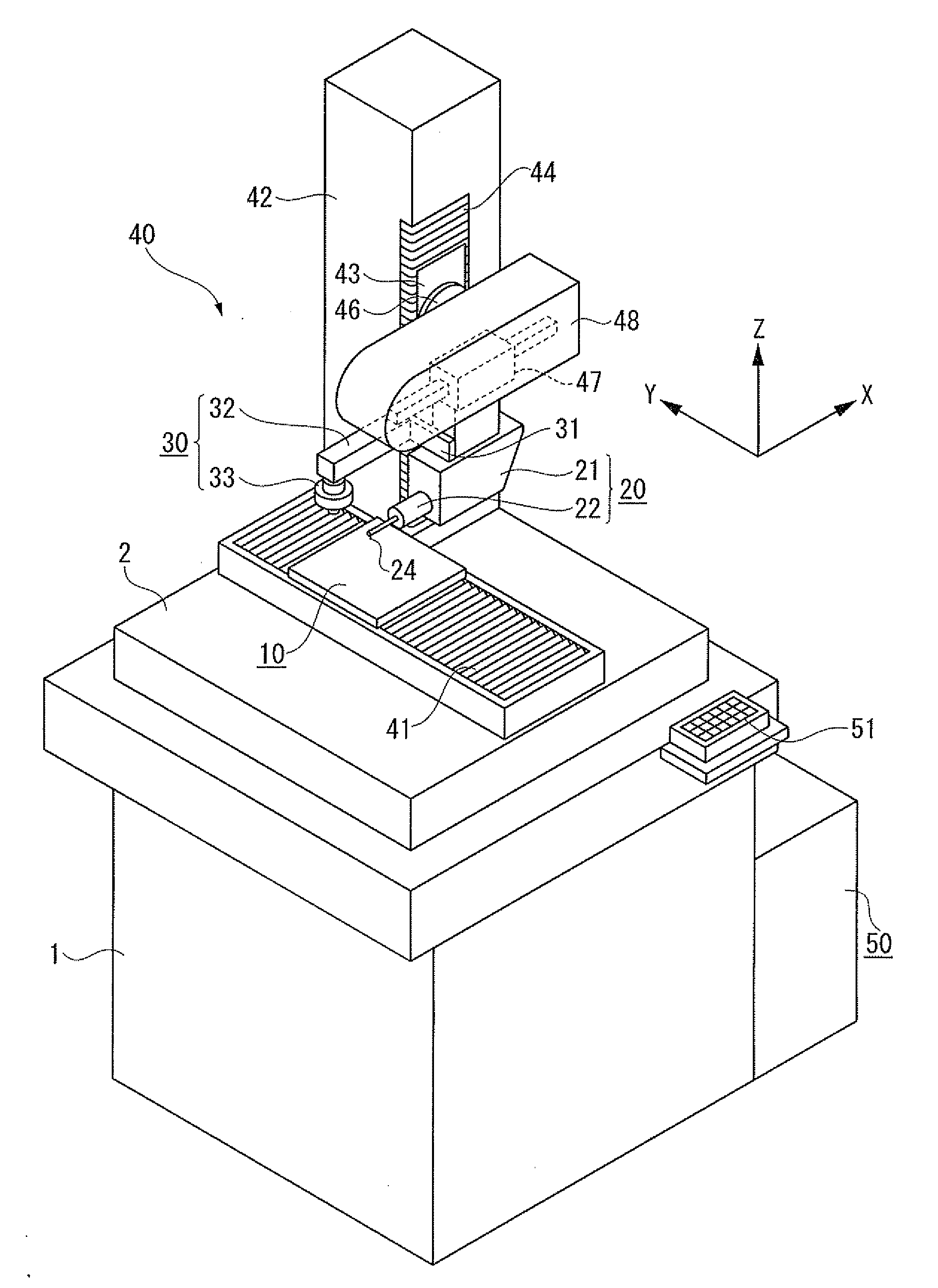
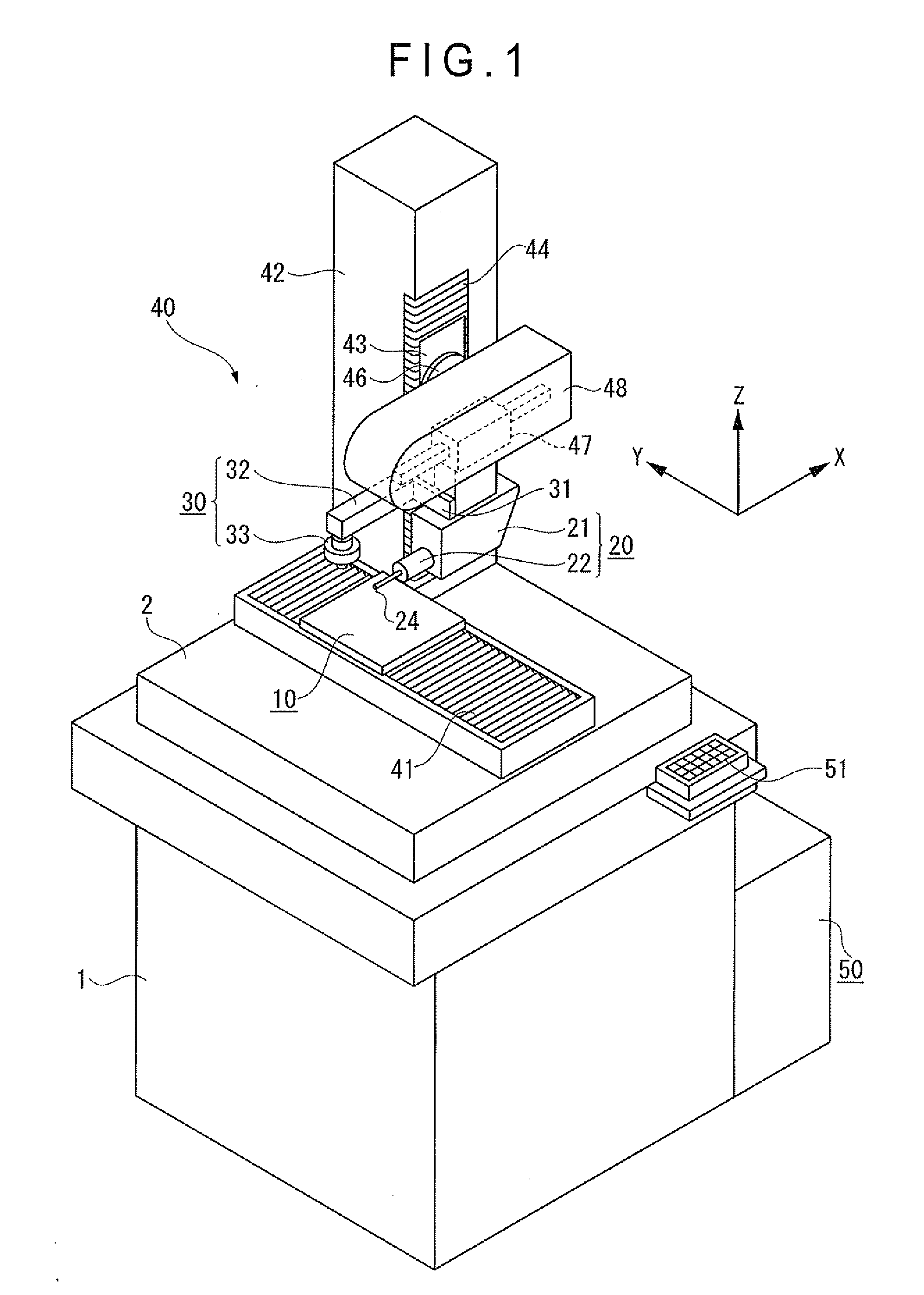
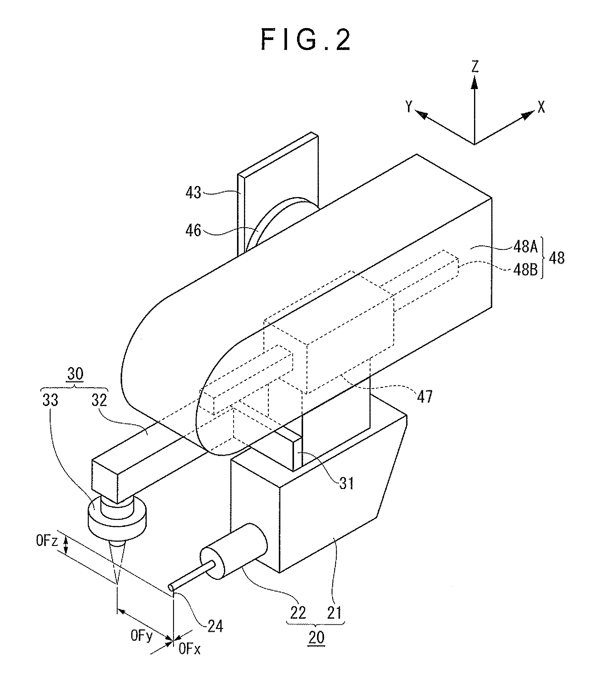
[0113]In the surface texture measuring machine including the contact-type detector 20 having the stylus 24 and the image probe 30 according to the first exemplary embodiment, when the operator operates the relative movement mechanism 40 to acquire the position data of at least three point of the circular contour of the circular concave portion 61 of the object 60A by the image probe 30, the controller 50 approximates the entered position data to the circle 63 to obtain the center position C of the circle 63, and then operates the relative movement mechanism 40 to position the stylus 24 of the contact-type detector 20 at the center position C.

[0114]In this manner, the stylus 24 of the contact-type detector 20 can be automatically set at the center position C of the circular concave portion 61 of the object 60A. In other words, the operator does not have to position the tip end of the stylus at the circular concave portion while visually checkin...

first exemplary embodiment (see figs.12 to 17)

Modifications of First Exemplary Embodiment (see FIGS. 12 to 17)

[0123]The object to be measured is not limited to the object shown in FIGS. 6A and 6B. For instance, the object may be an object 60B including a circular convex portion 62 at a center thereof. The circular convex portion 62 has a circular contour and a spherical and convex interior.

[0124]A surface texture of the circular convex portion 62 of the object 60B is measured as shown in FIGS. 13 to 17.

[0125](11) As shown in FIG. 13, the relative movement mechanism 40 is operated to move the circular convex portion 62 of the object 60B within a view field 64 of the image probe 30.

[0126](12) As shown in FIGS. 14A and 14B, in the vicinity of the circular convex portion 62 of the object 60B, the objective lens 35 of the image probe 30 is automatically focused so as to set the focal point of the objective lens 35 near the circular convex portion 62 of the object 60B and data D1, D2, D3 and so on of at least three points of the circ...

second exemplary embodiment

Advantages of Second Exemplary Embodiment

[0157]According to the second exemplary embodiment, what is carried out in the preliminary measurement is only that the image probe 30 captures the image of the object W to calculate the inclination angle θ of the object W relative to the measurement axis A. Accordingly, the number of the steps in the preliminary measurement can be decreased, thereby shortening the time for the preliminary measurement. Moreover, since the measurement is carried out by the image probe 30, the measurement time can be shortened as compared with the measurement by the stylus 24. Consequently, the time for the preliminary measurement can be considerably shortened.

[0158]Further, since the preliminary measurement is a noncontact measurement by the image probe 30, the object W is not damaged.

Modification(s) of Second Exemplary Embodiment

[0159]A table mounted on the stage is not limited to the table shown in FIG. 20.

[0160]For instance, the surface texture measuring me...


PUM


Abstract

A surface texture measuring machine includes: a stage, a contact-type detector having a stylus, an image probe, a relative movement mechanism and a controller. The controller includes: a center position calculating unit that, when the image probe enters position data of at least three points on a circular contour of a circular concave portion or a circular convex portion of an object, approximates the entered position data to a circle to obtain a center position of the circle; and a stylus setting unit that, after calculating the center position, operates the relative movement mechanism to position the stylus of the contact-type detector at the center position.

Description

[0001]The entire disclosure of Japanese Patent Applications No. 2009-236121 filed Oct. 13 2009, No. 2009-236123 filed Oct. 13 2009, No. 2009-236124 filed Oct. 13 2009, and No. 2009-236125 filed Oct. 13 2009, are expressly incorporated by reference herein.BACKGROUND OF THE INVENTION[0002]1. Field of the Invention[0003]The present invention relates to a surface texture measuring machine for measuring surface profiles, surface roughness and the like of an object to be measured and a surface texture measuring method. Specifically, the present invention relates to a surface texture measuring machine including a contact-type detector provided with a stylus and an image probe, and a surface texture measuring method.[0004]2. Description of Related Art[0005]There has been known a surface texture measuring machine in which a stylus is moved along a surface of an object while being in contact with the surface of the object. A displacement of the stylus due to a surface profile or surface rough...

Claims


Application Information

Patent Timeline
Patent Type & Authority Applications(United States)
IPC IPC(8): G01B5/28
CPCG01B5/008G01B21/047G01B11/245G01B11/005
Inventor MATSUMIYA, SADAYUKIOMORI, YOSHIYUKIARITA, SADAHARUHIRANO, KOTAROFUKUMOTO, YASUSHIKOMATSU, KOICHITAKEMURA, FUMIHIRO
Owner MITUTOYO CORP
Why Eureka
Try Eureka