
Lamp with magnifier

a technology of magnifiers and lamps, applied in the field of magnifiers, can solve the problems of small working area, poor flexibility of the lamp body, and difficulty in meeting the application needs of existing magnifying lamps, and achieve the effects of flexible use, wide magnification range, and large working area

Inactive Publication Date: 2011-04-14
LU JAMES
View PDF6 Cites 11 Cited by
  • Summary
  • Abstract
  • Description
  • Claims
  • Application Information

AI Technical Summary

Benefits of technology

[0012]The present invention is advantageous in that it has a wider magnification range and a larger working area, and being more flexible to use and widely applicable.

Problems solved by technology

Even with improvements in the movable connection between the lamp arm and the base, the disadvantages of small working area and poor flexibility of the lamp body still persist.
Besides, for magnifying lamps with a wider range of magnification, it is difficult for existing magnifying lamps to fulfill the application needs.

Method used


Image

  • Lamp with magnifier
  • Lamp with magnifier

Examples


Embodiment Construction

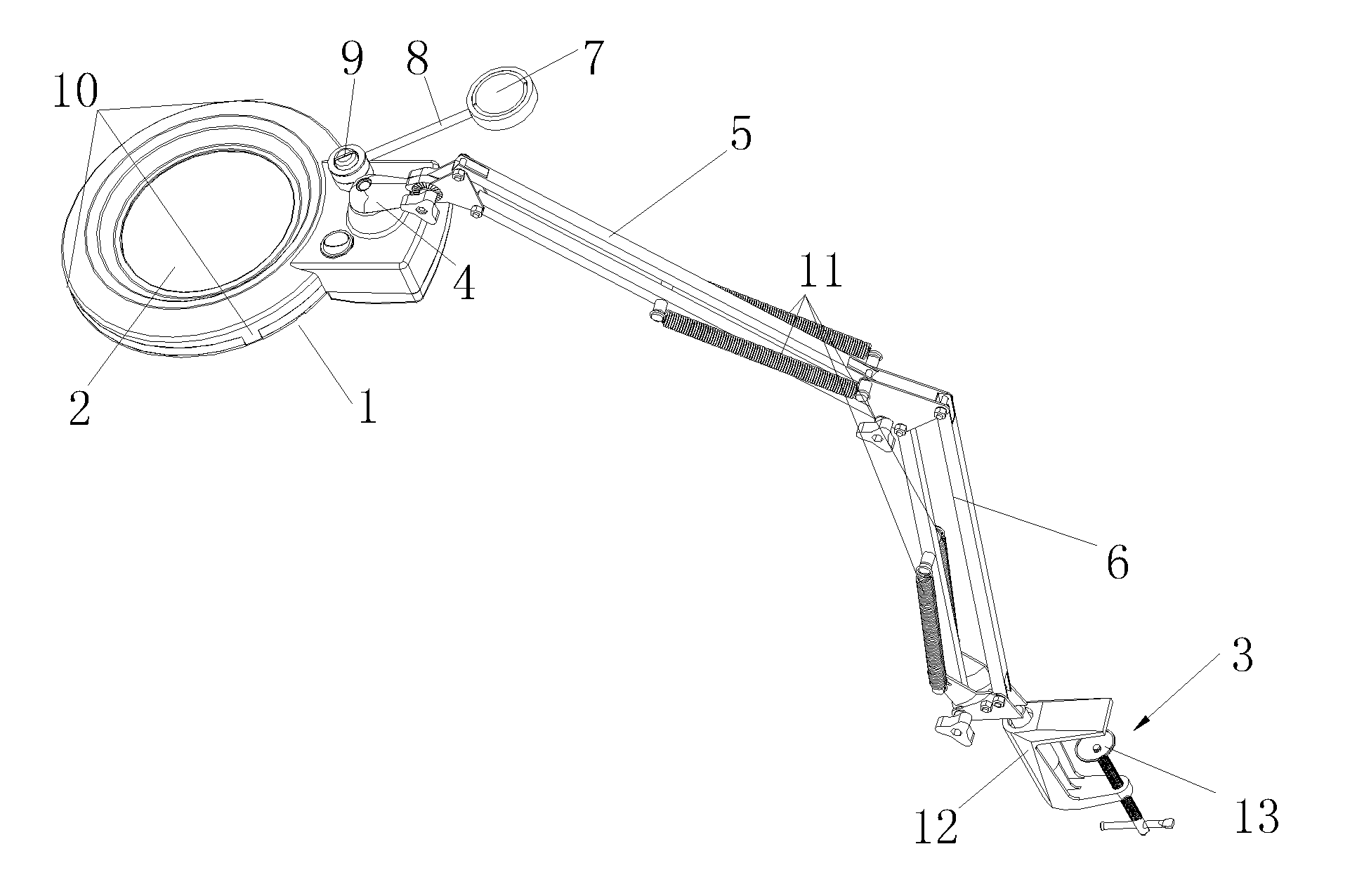
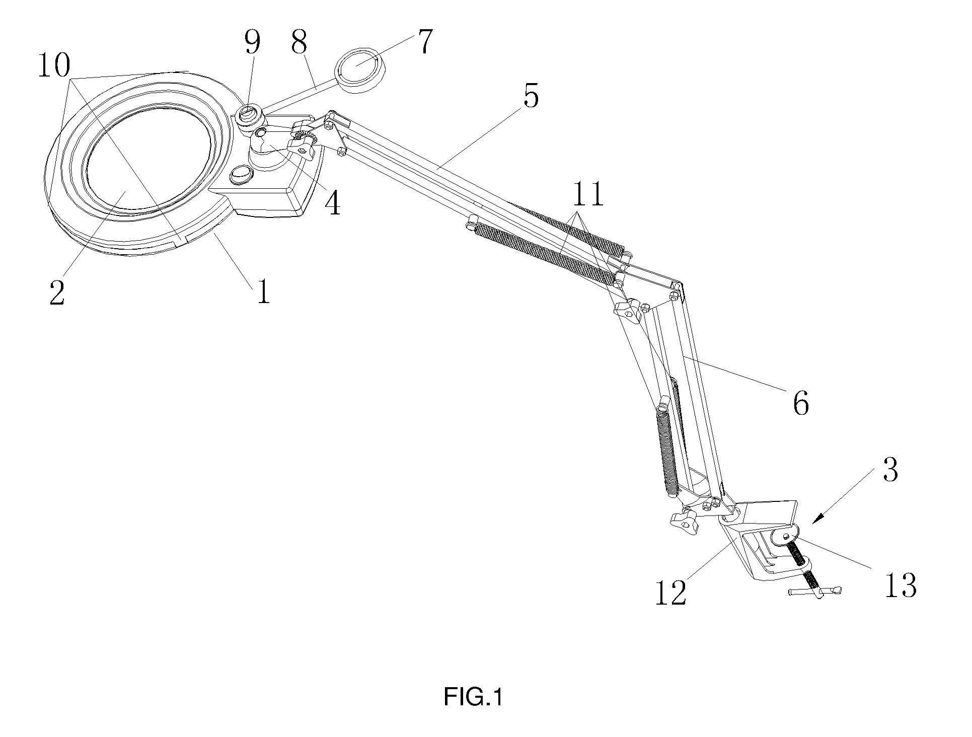
[0015]As illustrated in FIG. 1, the lamp with magnifier comprises a lighting lamp, a lampshade 1, a magnifying lens 2, a lamp arm and a lamp body fixing means 3. The lighting lamp is fixedly disposed under the lampshade 1. The magnifying lens 2 is disposed in a central position of the lampshade 1. The lampshade 1 is movably connected with an upper end of the lamp arm and rotatable in a vertical plane. The lampshade 1 is connected to the upper end of the lamp arm via a first rotating shaft 4. The lampshade 1 is freely rotatable in a horizontal plane around the first rotating shaft 4. The lamp arm comprises an upper lamp arm 5 and a lower lamp arm 6. The upper lamp arm 5 and the lower lamp arm 6 are movably connected with each other forming an adjustable angle in between. The lower lamp arm 6 is movably connected to the lamp body fixing means 3. The lower lamp arm 6 is rotatable in a horizontal plane relative to the lamp body fixing means 3.

[0016]A second magnifying lens is disposed a...


PUM


Abstract

The present invention provides a lamp with magnifier which has a lighting lamp, a lampshade, a magnifying lens, a lamp arm and a lamp body fixing means; the lighting lamp is fixedly disposed under the lampshade; the magnifying lens is disposed in a central position of the lampshade; the lampshade is movably connected with an upper end of the lamp arm via a first rotating shaft and rotatable in a vertical plane; the lampshade is freely rotatable around the first rotating shaft in a horizontal plane; the lamp arm comprises an upper lamp arm and a lower lamp arm which are movably connected with each other forming an adjustable angle in between; the lower lamp arm is movably connected with the lamp body fixing means, and the lower lamp arm is rotatable in a horizontal plane relative to the lamp body fixing means.

Description

BACKGROUND OF THE INVENTION[0001]The present invention relates to a lamp with magnifier for magnified observation.[0002]A lamp with magnifier generally comprises a magnifying lens, a lighting lamp, a power supply for the lighting lamp and a base. The light source generally comprises cold cathode fluorescent lamps or a plurality of light emitting diodes, and it is disposed at the outer periphery of the magnifying lens. The power source converts alternating current of 110V / 220V to direct current of a safe voltage for the light source, so that dangerous voltage is separated from the magnifying lamp. The base is made of insulating plastic material in general. It is provided with a handle for installing the lighting lamp, the magnifying lens, the adjusting and controlling circuit for the power supply and the switch and for hand-held purposes. As the present invention consumes little electricity and has low voltage, it is safe for human. In combination with the magnifying lens, the presen...

Claims


Application Information

Patent Timeline
IPC IPC(8): F21S8/00
CPCF21V21/06G02B25/02F21V33/00F21V21/28
Inventor LU, JAMES
Owner LU JAMES
Learn More