Floor treatment cleaning systems

a cleaning system and floor technology, applied in the direction of cleaning using liquids, photosensitive materials, instruments, etc., can solve the problems of high power consumption, limited diameter, and limited tool pressure and tool diameter

Active Publication Date: 2012-06-19
JOHNSONDIVERSEY INC
View PDF18 Cites 13 Cited by
  • Summary
  • Abstract
  • Description
  • Claims
  • Application Information

AI Technical Summary

Benefits of technology

[0006]It is thus an object of the present invention to provide a floor treatment cleaning system which combines the advantages of the different prior art systems without being subject to their problems.
[0007]This is achieved by a floor treatment cleaning system with apparatus which utilizes an eccentrical drive for a rotational non-vibrating movement of the treatment elements in order to achieve a uniform cleaning result over a large working area and an efficient transportation of dirt and cleaning solution in a determined direction with less power consumption.

Problems solved by technology

Firstly, tool pressure and tool diameter are limited: the maximum tool pressure is defined by the machine weight minus the necessary weight for sufficient traction and in some cases also by pressure needs due to the suction system; the diameter is limited by the effect of centrifugal forces.
Furthermore, the drive performance of the motor increases with the pressure—this influences motor size, costs and machine autonomy: for many cleaning purposes, a high weight is needed which results in a high power consumption.
However, cylindrical systems have other drawbacks.
Firstly, the tools are very expensive and have a highly restricted versatility.
Secondly, the contact area with the floor is very small: thus, at a higher moving speed of the machine, the agitation time becomes very short.
Furthermore, the relative cleaning speed of the bristles can be zero over the whole length of the tool and the overall cleaning result is worse.
Finally, cylindrical systems have a high power consumption.
Although the cleaning means according to this system have a large contact area with the floor and constant agitation parameters almost over the full cleaning area, they undergo a randomly vibrating movement which does not provide for an efficient transportation of dirt and cleaning solution in a determined direction.
However, since GB 516 405 is concerned with polishing or grinding an already clean surface and not with cleaning it from dirt, it is not disclosed how the dirt is actually removed.

Method used


Image

  • Floor treatment cleaning systems
  • Floor treatment cleaning systems
  • Floor treatment cleaning systems

Examples


first embodiment

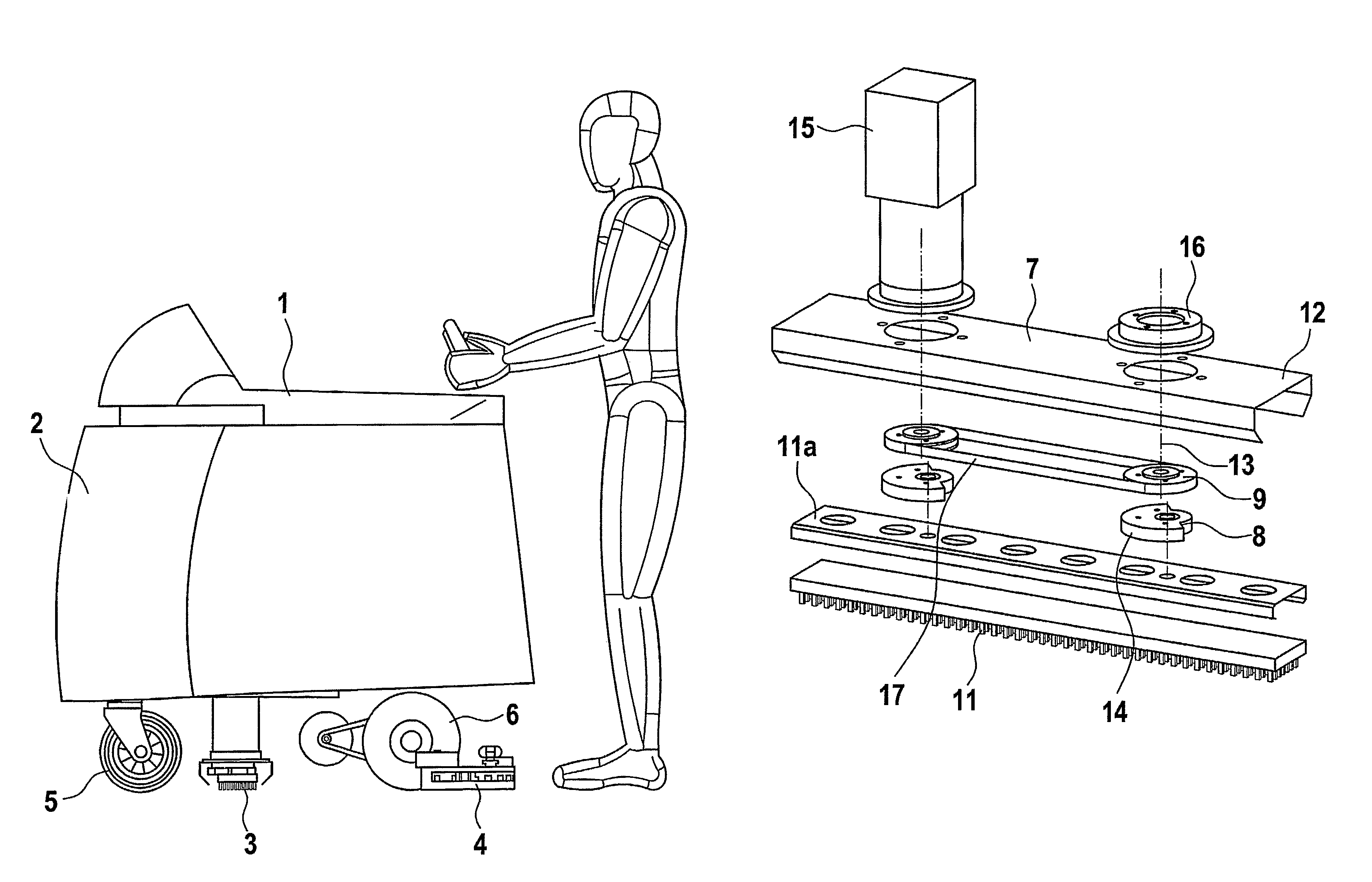
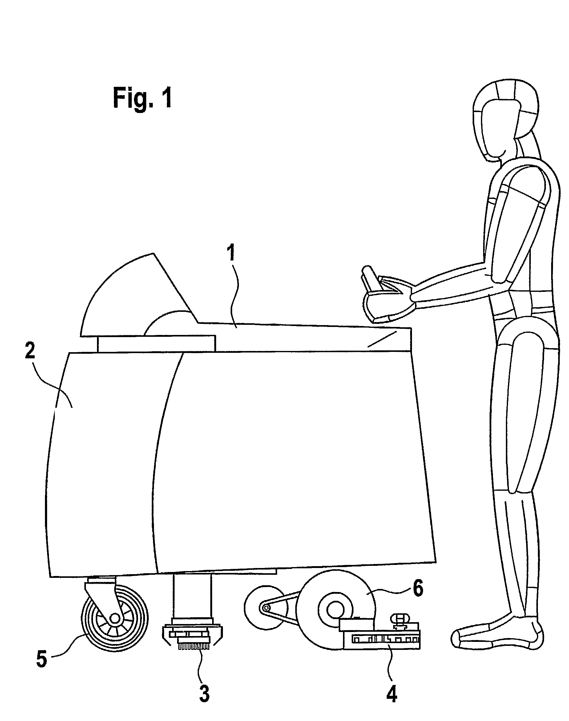
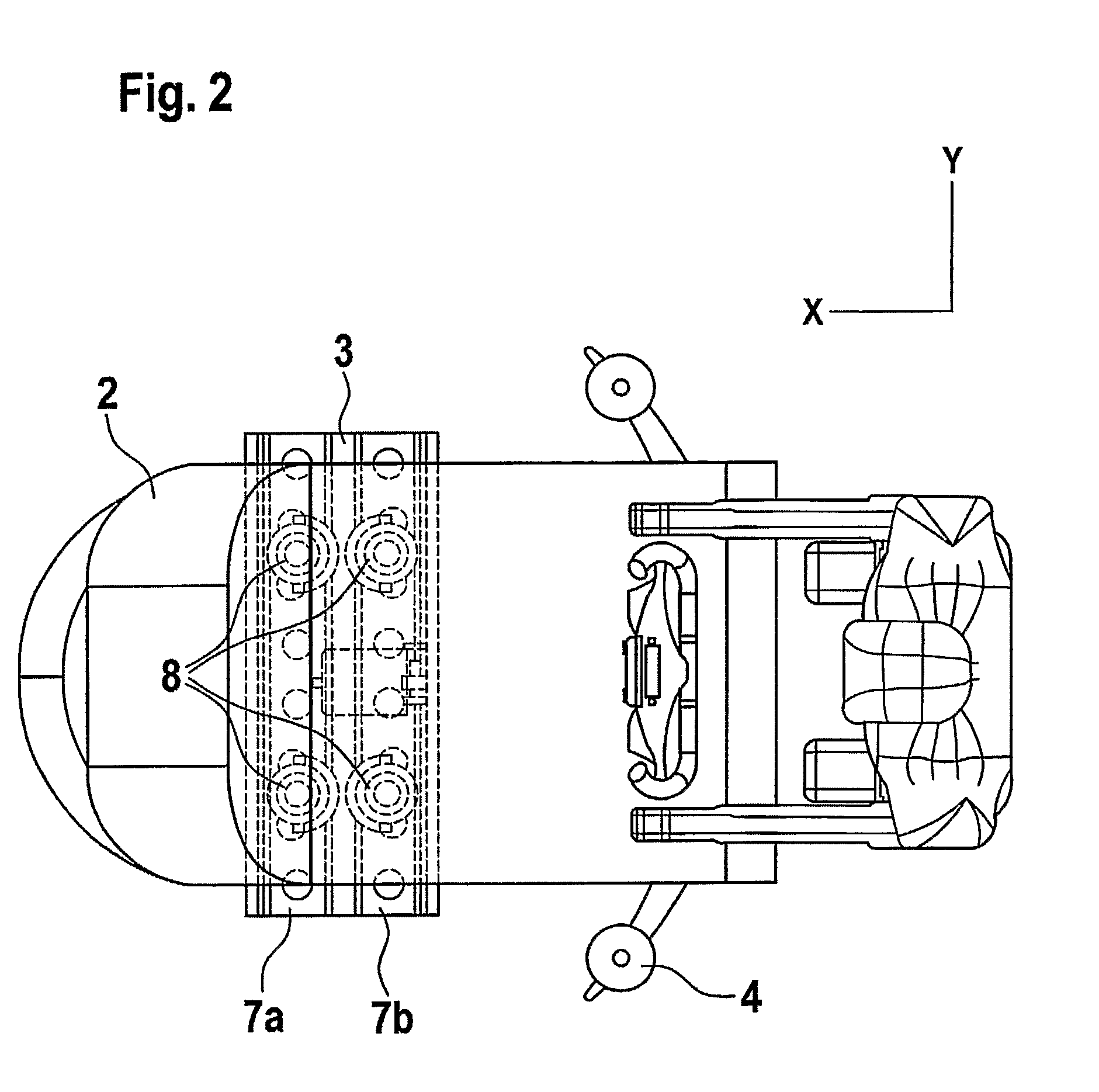
[0017]FIGS. 1 and 2 illustrate a cleaning machine which is equipped with a floor treatment cleaning system according to the present invention. The floor cleaning machine 1 comprises a tank 2, a floor treatment cleaning system 3 and a suction foot (squeegee) 4 behind the treatment cleaning system. The machine runs on a front wheel 5 and two rear wheels 6. the floor treatment cleaning system comprises two treatment elements 7a and 7b which are arranged transversely relative to the moving direction of the machine 1 and in parallel behind each other (as can be seen in more detail in FIG. 2). The elements are each driven by two eccentric pivots 8.

[0018]FIG. 3 shows that the two eccentrically driven treatment elements 7a and 7b are interconnected via four synchronization pulleys 9 and a system synchronization belt 10. As can be seen, the treatment elements 7a, 7b are arranged with a phase shift of 180°, i.e., the pivots of treatment element 7a and the pivots of treatment element 7b are l...

fourth embodiment

[0025]FIG. 7 shows a top view of a floor cleaning machine which is equipped with the floor treatment cleaning system according to the present invention. This embodiment is similar to the second and third, except for the treatment elements being arcuate.

[0026]FIG. 8 shows a top view of a floor cleaning machine which is equipped with a fifth embodiment of the floor treatment cleaning system according to the present invention. In this embodiment (which can be considered as a combination of the first and third embodiments), two sets each consisting of two treatment elements 7a, 7a′ and 7b, 7b′, resp., are arranged in a V-shape with the opening in the moving direction of the machine. In operation, the left treatment elements 7a, 7a′ relative the moving direction of the machine are driven to perform a clockwise constrained rotation, whereas the right treatment elements 7b, 7b′ are driven to perform a counterclockwise constrained rotation. The treatment elements of each set are synchronize...


PUM


Abstract

Floor treatment cleaning system (3) for a floor cleaning machine (1). The floor treatment cleaning system includes at least two treatment elements (7a, 7b) wherein each treatment element is equipped with cleaning means (11) and is eccentrically driven by driving means (15A) via at least two synchronized eccentric pivots (8), characterized in that the respective pivots revolve around their main rotation axes (13) in such a way that the at least two treatment elements perform opposite movements thereby transporting residues on the floor in a desired direction and balancing engine masses and friction. The treatment elements (7a, 7b) can be positioned in different ways: transversely relative to the moving direction of the machine (1) and parallel behind each other, transversely relative to the moving direction of the machine (1) and next to each other and in a V-shape or arcuate with the opening in the moving direction of the machine.

Description

TECHNICAL FIELD[0001]The present invention relates to a floor treatment cleaning system.BACKGROUND AND STATE OF THE ART[0002]Various systems for cleaning floor surfaces are known. At present, the two most common systems on the market are disc systems and cylindrical systems. Disc systems comprise a flat disc being fitted with brushes or pads which is rotated around an axis perpendicular to the surface plane. Having the advantage of a large contact area with the floor and being very flexible concerning the adaptation to different cleaning tasks due to a variety of pad / brush configurations, disc systems have the following drawbacks, though. Firstly, tool pressure and tool diameter are limited: the maximum tool pressure is defined by the machine weight minus the necessary weight for sufficient traction and in some cases also by pressure needs due to the suction system; the diameter is limited by the effect of centrifugal forces. Furthermore, the drive performance of the motor increases...

Claims


Application Information

Patent Timeline
Patent Type & Authority Patents(United States)
IPC IPC(8): A47L11/283A47L11/284A47L11/294A47L11/12
CPCA47L11/12A47L11/4036A47L11/4069
Inventor MAYER, HEINRICH-TITO
Owner JOHNSONDIVERSEY INC
Why Eureka
Try Eureka