Mounting device for disk-shaped rotating tool

a technology of rotating tools and mounting devices, which is applied in the direction of grinding carriages, grinding machine components, manufacturing tools, etc., can solve the problems of large impact applied to operators, physical adverse effects on operators, and difficult operations, and achieve the effect of reducing vibrations during the operation of tools and simple structur

Inactive Publication Date: 2011-04-14
TENRYU SAW MFG
View PDF17 Cites 40 Cited by
  • Summary
  • Abstract
  • Description
  • Claims
  • Application Information

AI Technical Summary

Benefits of technology

[0007]It is therefore an object of the present invention to provide a mounting device for a disk-shaped rotating tool which can reduce the vibrations during the operation of the tool with a simple structure.

Problems solved by technology

During such operations, a large impact is applied to an operator.
In a conventional grinding disk, such a large impact is directly transmitted to the operator, making the operations difficult and having a physically adverse effect on the operator due to vibrations.
Accordingly, the formation of the annular groove is difficult and the rigidity of the shock absorbing ring is reduced by the formation of the annular groove.

Method used


Image

  • Mounting device for disk-shaped rotating tool
  • Mounting device for disk-shaped rotating tool
  • Mounting device for disk-shaped rotating tool

Examples


Embodiment Construction

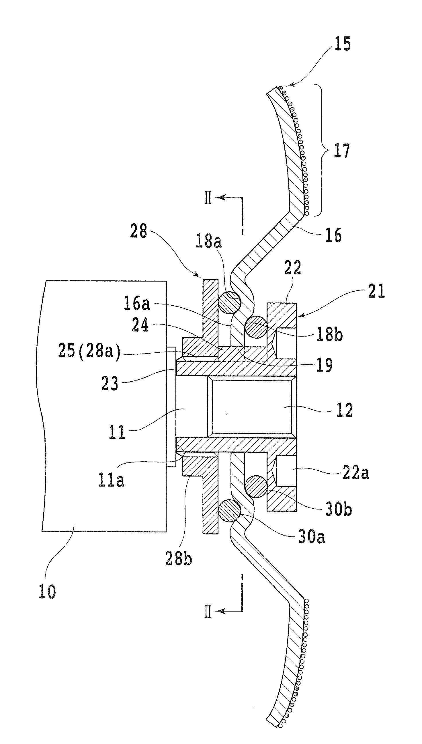
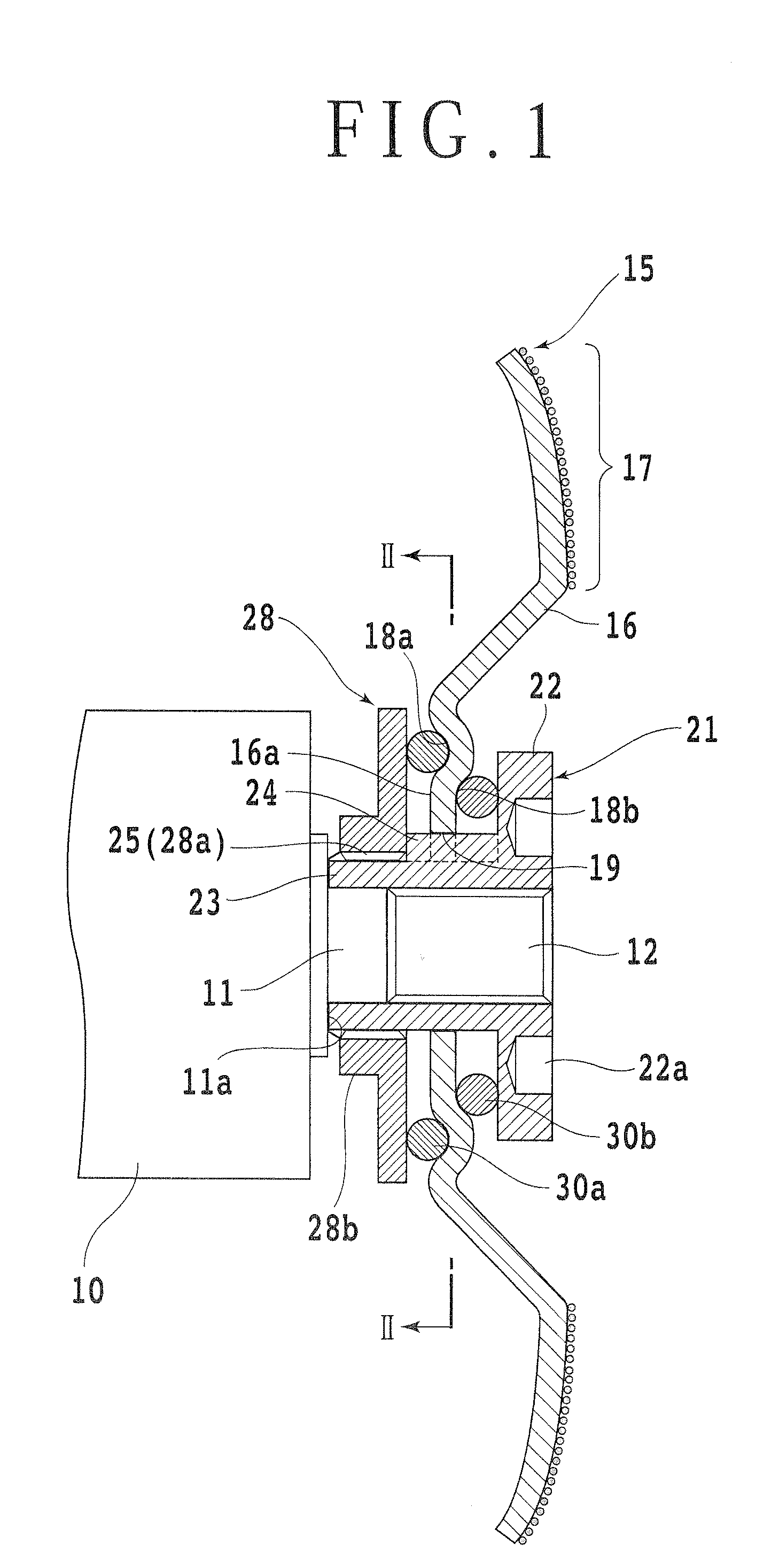
[0016]Some preferred embodiments of the present invention will now be described in detail with reference to the drawings. Referring to FIG. 1, there is shown a first preferred embodiment of the present invention, wherein reference numeral 10 denotes a case of an electric rotary machine such as a disk grinder. An output shaft 11 of the electric rotary machine projects from the case 10. The base end portion of the output shaft 11 is stepped to form a seating surface 11a, and a small-diameter screw shaft 12 projects from the seating surface 11a.

[0017]The present invention provides a device for mounting a disk-shaped rotating tool 15 such as a grinding disk through a pair of first and second holding members 21 and 28 to the output shaft 11 of the electric rotary machine. In this preferred embodiment, the disk-shaped rotating tool 15 is provided by a grinding disk. The grinding disk 15 is composed of a base plate 16 formed from a steel plate and super-hard abrasive grains fixed to the o...


PUM


Abstract

An annular retaining groove is formed on the inner circumferential portion of the disk-shaped rotating tool, and a ringlike cushioning member is fitted in this annular retaining groove so as to be partially exposed. Both sides of the inner circumferential portion of the disk-shaped rotating tool are held by first and second holding members through the annular cushioning member. An axial portion of the first holding member is engaged with an output shaft of an electric rotary machine so that the disk-shaped rotating tool is rotated through the first holding member by the output shaft.

Description

BACKGROUND OF THE INVENTION[0001]1. Field of the Invention[0002]The present invention relates to a device for mounting a disk-shaped rotating tool such as a grinding disk and a circular saw to an output shaft of an electric rotary machine in the condition that the tool is held from both sides thereof under elastic pressure.[0003]2. Description of the Related Art[0004]A grinding disk mounted on an output shaft of an electric rotary machine is used for leveling of the plane surface of a concrete, building material, and stone material, etc. or for any other various operations such as chamfering, repairing of a building wall surface, and removing of a painted surface. During such operations, a large impact is applied to an operator. In a conventional grinding disk, such a large impact is directly transmitted to the operator, making the operations difficult and having a physically adverse effect on the operator due to vibrations.[0005]To prevent such a physically adverse effect on the op...

Claims


Application Information

Patent Timeline
Patent Type & Authority Applications(United States)
IPC IPC(8): B24B41/02
CPCB24B45/006B27B5/32B24D7/16
Inventor TAKEMURA, SOKICHINAKAGAWA, AKIHIKO
Owner TENRYU SAW MFG
Why Eureka
Try Eureka