
Hydraulic Actuator Unit

a technology of actuators and actuators, applied in the direction of fluid couplings, positive displacement liquid engines, liquid fuel engines, etc., can solve the problems of patent application publication, patent application publication, patent application publication, etc., and the assembling workability of the first and second electric motors is worsened

Active Publication Date: 2011-04-21
KANZAKI KOKYUKOKI MFG
View PDF101 Cites 10 Cited by
  • Summary
  • Abstract
  • Description
  • Claims
  • Application Information

AI Technical Summary

Benefits of technology

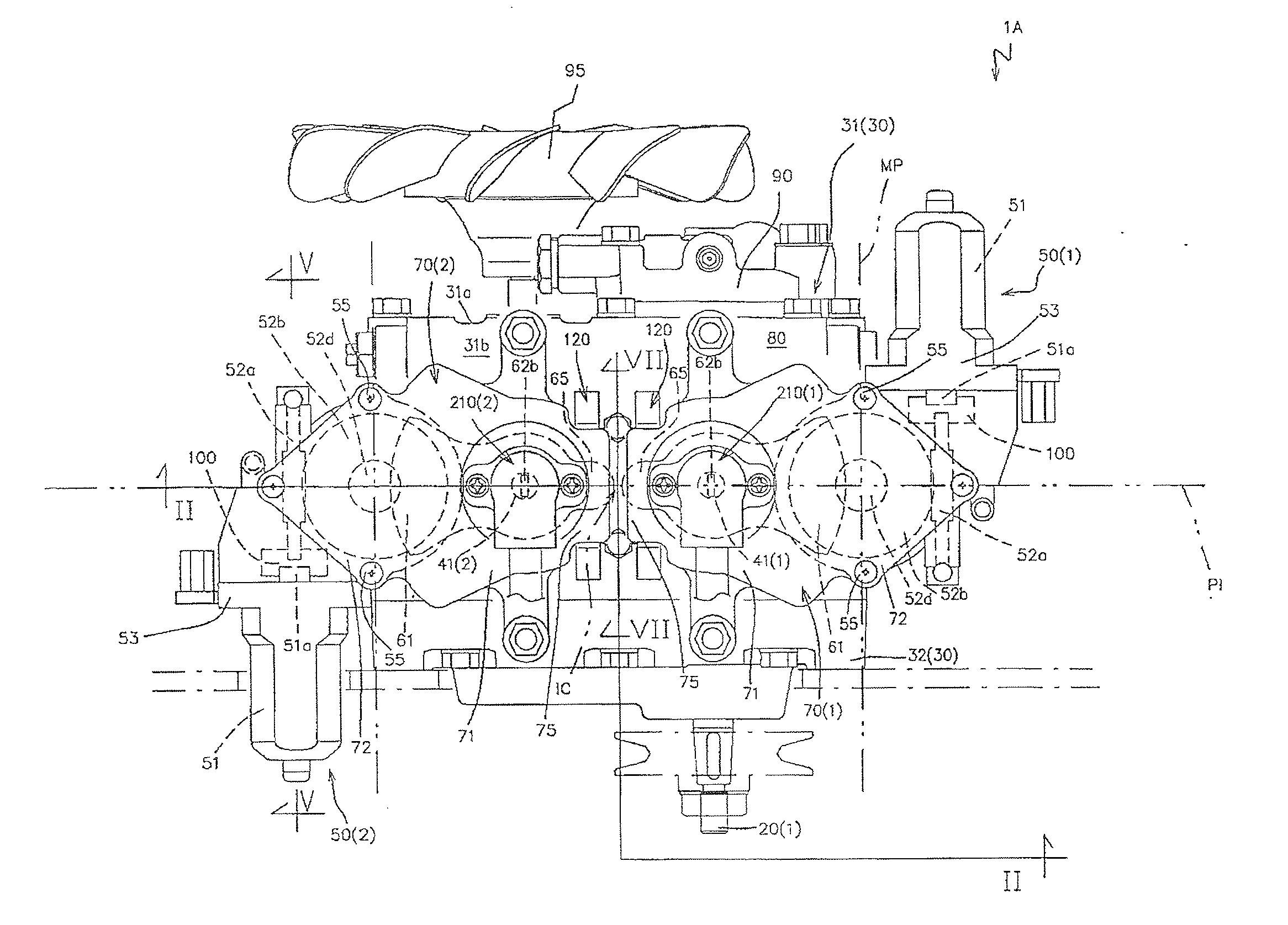
[0021]The hydraulic actuator unit according to the present invention makes it possible to mount the first electric motor assembly to the pump case while preventing the first electric motor assembly from being interfered with a transmission mechanism transmitting rotational power from the driving power source to the first end of the first pump shaft without elongating a length of a portion of the first end of the first pump shaft that is extended outward from the pump case. The hydraulic actuator unit makes it also possible to mount the second electric motor assembly to the pump case while preventing the second electric motor assembly from being interfered with the cooling fan supported by the second end of the second pump shaft without elongating a length of a portion of the second end of the second pump shaft that is extended outward from the pump case. Accordingly, the hydraulic actuator unit could be reduced in size as a whole.
[0040]The provision of the clutch structure makes it also possible to prevent unintentional rotation of the electric motor output gear, that is unintentional rotation of the control shaft, at the time when the electric motor main body is in a non-operated state.

Problems solved by technology

However, the hydraulic actuator unit disclosed in the US patent application publication has following problems.
Accordingly, in the conventional hydraulic actuator unit, it is likely to cause a mistake in assembling work of the first and second electric motors to the pump case, resulting in worsened assembling workability of the first and second electric motors while involving complicated inventory management of the first and second electric motor covers.
Furthermore, the conventional hydraulic actuator unit does not take into account cases where the variable displacement mechanism needs to be manually operated upon breakdown or mode change of the electric motor.
Therefore, the conventional hydraulic actuator unit has difficulties in changing modes between the electric mode of actuating the variable displacement mechanism with use of the electric motor and the manual mode of manually actuating the variable displacement mechanism.

Method used


Image

  • Hydraulic Actuator Unit
  • Hydraulic Actuator Unit
  • Hydraulic Actuator Unit

Examples


first embodiment

[0072]Hereinafter, a preferred embodiment of a hydraulic actuator unit according to the present application will be explained with reference to the accompanying drawings.

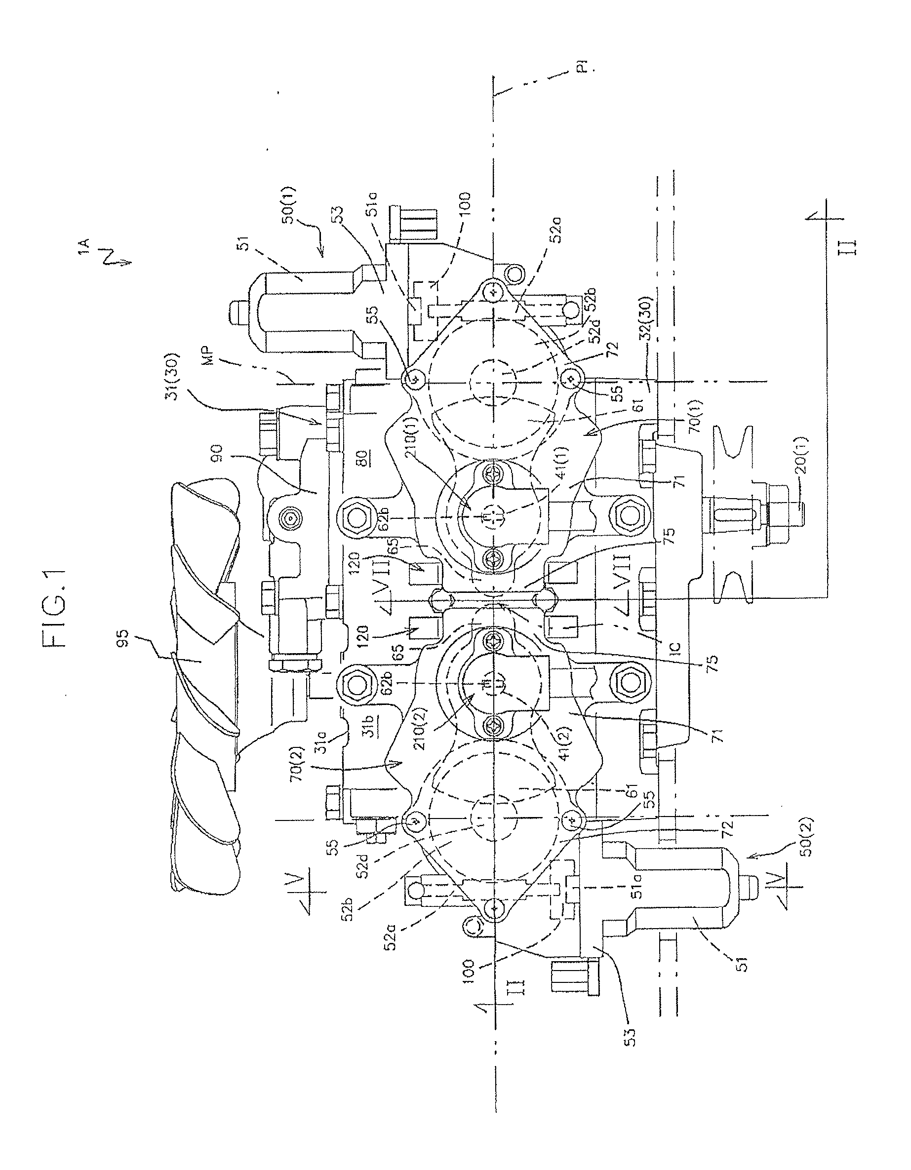
[0073]FIG. 1 is a front view of a hydraulic actuator unit 1A according to the present embodiment.

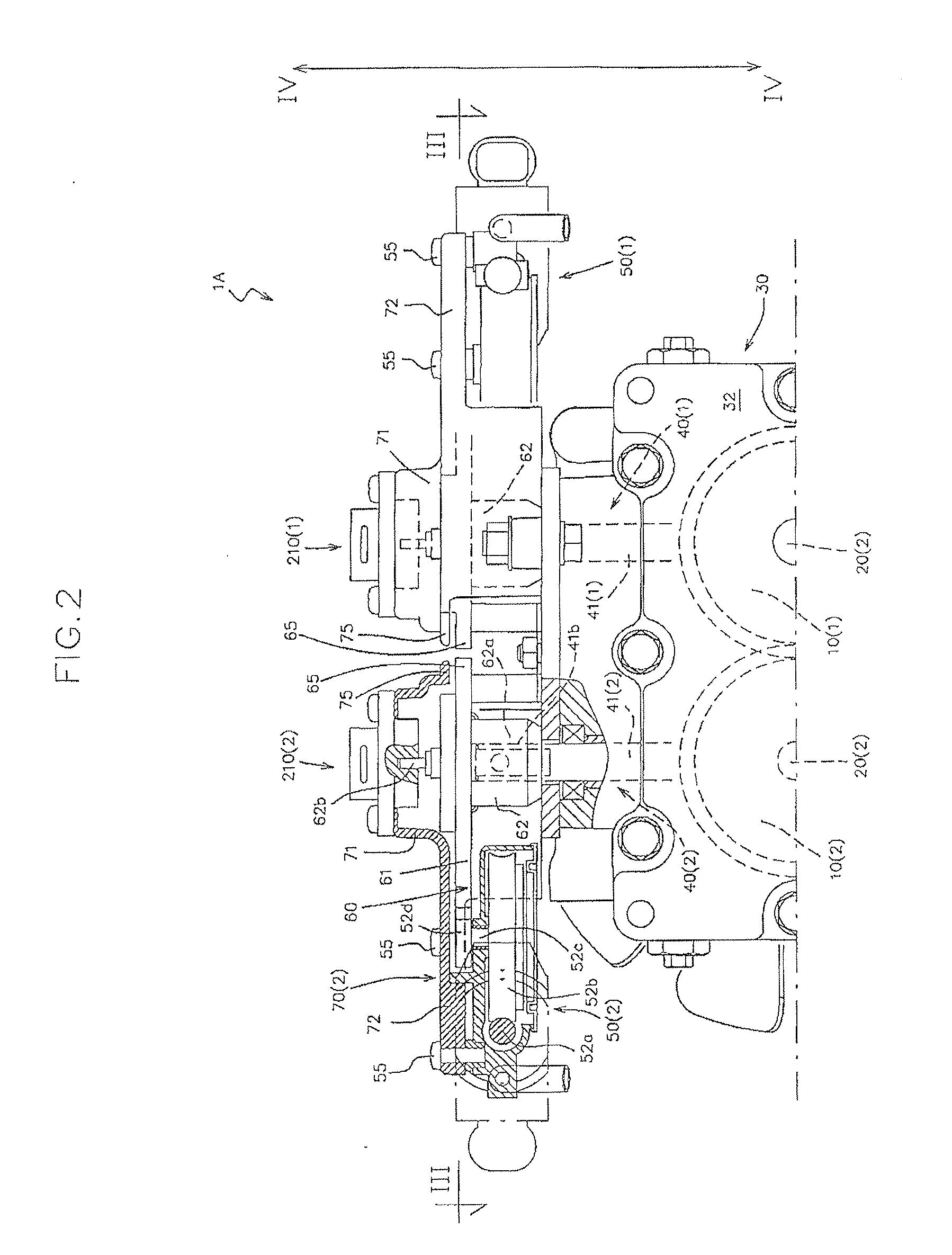
[0074]FIGS. 2 and 3 are cross sectional views taken along line II-II in FIG. 1 and line III-III in FIG. 2, respectively.

[0075]Further, FIG. 4 is an exploded perspective view of the hydraulic actuator unit 1A taken along line IV-IV in FIG. 2.

[0076]The hydraulic actuator unit 1A includes a rotary shaft, a hydraulic actuator that is supported by the rotary shaft in a relatively non-rotatable manner with respect thereto, a variable displacement mechanism 40 that changes the displacement of the hydraulic actuator, and an electric motor 50 that actuates the variable displacement mechanism 40.

[0077]As shown in FIGS. 1 to 3, the hydraulic actuator unit 1A according to the present embodiment is formed as a hydraulic pump unit tha...

second embodiment

[0338]Hereinafter, another embodiment of the hydraulic actuator unit according to the present application will be explained with reference to the accompanying drawings.

[0339]FIG. 27 is a plan view of a hydraulic actuator unit 2 according to the present embodiment.

[0340]FIGS. 28 and 29 are cross sectional views taken along lines XXVIII-XXVIII and XXIX-XXIX in FIG. 27, respectively.

[0341]In the drawings, the members same as those in the first embodiment are denoted by the same reference numerals to omit detailed description thereof.

[0342]As shown in FIGS. 27 to 29, the hydraulic actuator unit 2 according to the present embodiment is in the form of an axle driving device that integrally includes the hydraulic pump main body 10 of variable displacement type and a hydraulic motor main body 310 forming an HST in cooperation with the hydraulic pump main body 10.

[0343]The axle driving unit 2 is provided to each of the driving wheels of a working vehicle.

[0344]For example, as shown in FIG. 2...


PUM


Abstract

In the hydraulic actuator unit according to the present invention, a first electric motor assembly formed by mounting one of a pair of electric motors to one of a pair of electric motor covers is detachably mounted to a pump case so as to rotate a first control shaft around its axis line, and a second electric motor assembly formed by mounting the other one of the pair of electric motors to the other one of the pair of electric motor covers is detachably mounted to the pump case so as to rotate a second control shaft around its axis line. The first electric motor assembly is mounted to the pump case so that the corresponding electric motor has a rotational axis line in parallel with the first pump shaft in a state where the electric motor is positioned on an opposite side to the second control shaft with respect to the first control shaft and is also positioned on an opposite side to a first end of a first pump shaft with respect to a virtual plane that passes through the axis lines of the first and second control shafts. The second electric motor assembly is mounted to the pump case at a posture obtained by rotating the first electric motor assembly by 180 degrees about a virtual center line that is disposed in parallel with the first and second control shafts and is located at a center between the first and second control shafts, thereby the electric motor is positioned on an opposite side to a cooling fan, which is driven by the second end of the second pump shaft, with respect to the virtual plane.

Description

BACKGROUND OF THE INVENTION[0001]1. Field of the Invention[0002]The present invention relates to a hydraulic actuator unit including a hydraulic actuator such as a hydraulic pump main body, variable displacement mechanism for changing a displacement of the hydraulic actuator, and an electric motor for actuating the variable displacement mechanism.[0003]2. Related Art[0004]With regard to a hydraulic actuator unit such as a hydraulic pump unit or an HST unit, which includes a hydraulic actuator such as a hydraulic pump main body and a variable displacement mechanism for changing a displacement of the hydraulic actuator, there has been proposed a configuration in which the variable displacement mechanism is actuated with use of an electric motor (for example, US Patent Application Publication No. 2006-0272495).[0005]The conventional hydraulic actuator unit is useful in that operation force required for actuating the variable displacement mechanism could be reduced, since the electric m...

Claims


Application Information

Patent Timeline
IPC IPC(8): F04B1/32F01B3/02
CPCF04B1/20F04B1/295B60Y2200/223F04B53/22F16H61/435F04B1/324
Inventor SASAHARA, KENGOYASUDA, TOSHIFUMIKAMADA, MINORUINOUE, MASAAKINISHIZAWA, TAKASHIISHINO, FUMITOSHIITOU, MASAYAHIROSE, SHINICHIMATSUURA, JUNIWAIBARA, RYOTA
Owner KANZAKI KOKYUKOKI MFG
Learn More