
Puncture Repair Fluid Container and Puncture Repair Kit

a technology for puncture repair and fluid containers, which is applied in the field of puncture repair fluid containers and puncture repair kits, can solve the problems of less likely rotation of valves, deterioration etc., and achieve the effects of suppressing degradation of storage and cost performance, and reducing the risk of puncture damag

Active Publication Date: 2021-03-18
YOKOHAMA RUBBER CO LTD
View PDF0 Cites 0 Cited by
  • Summary
  • Abstract
  • Description
  • Claims
  • Application Information

AI Technical Summary

Benefits of technology

The present technology provides a puncture repair fluid container and a puncture repair kit that enable a switching knob to rotate easily at the time of puncture repair work. The switching knob has a tab portion that protrudes in the thickness direction of the switching knob body. The maximum height position of the tab portion is positioned outward of the center position of the switching knob body in the radial direction of the switching knob body. This makes it easier to grip and rotate the switching knob. The tab portion is preferably disposed outward of an outer diameter of the switching knob body in the radial direction of the switching knob body. The switching knob body can have at least one recessed portion or protruding portion that can fit or mate with the tab portion. This prevents unintentional rotation of the switching knob during storage.

Problems solved by technology

In a case of such a puncture repair fluid container, there arises a problem in that a switching knob for operating the switching valve is less likely to rotate when the hermeticity of the switching valve is high.
Here, a structure in which the maximum height position of the tab portion is at the center position of the switching knob body or the height of the tab portion is constant is disadvantageous in gripping the tab portion to rotate the switching knob.
However, when the switching knob itself is increased in size, storage and cost performance tends to be deteriorated.

Method used


Image

  • Puncture Repair Fluid Container and Puncture Repair Kit
  • Puncture Repair Fluid Container and Puncture Repair Kit
  • Puncture Repair Fluid Container and Puncture Repair Kit

Examples


Embodiment Construction

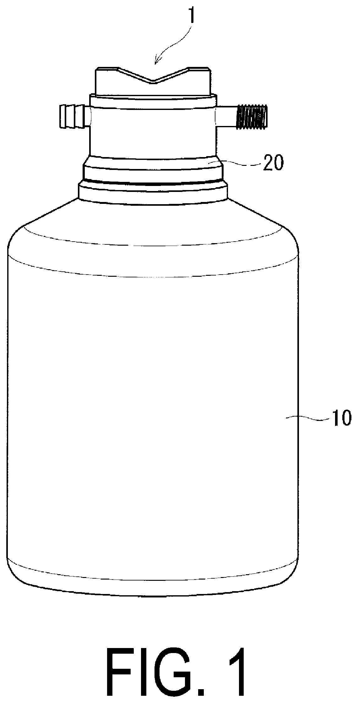
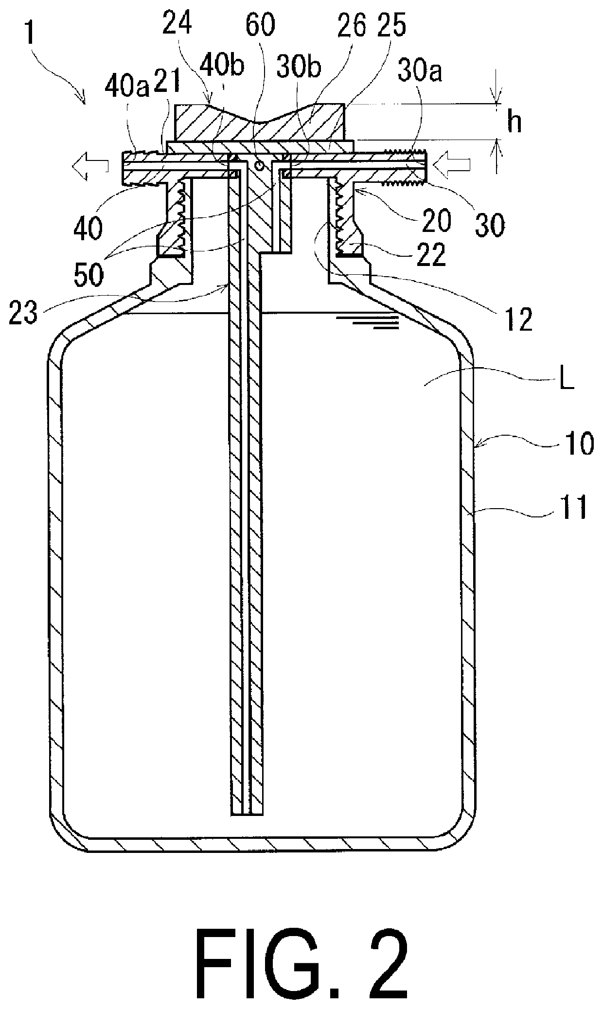
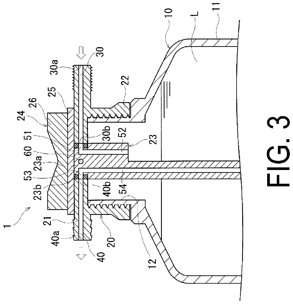
[0020]Configurations of embodiments of the present technology will be described in detail below with reference to the accompanying drawings. FIG. 1 to FIG. 4 illustrate a puncture repair fluid container according to an embodiment of the present technology. FIG. 5 illustrates a switching knob of the puncture repair fluid container according to the embodiment of the present technology.

[0021]As illustrated in FIG. 1 and FIG. 2, a puncture repair fluid container 1 (hereinafter, referred to as “container 1”) according to the present technology includes a container body 10 and a cap 20. A hose that connects the container 1 to a high-pressure air feed device and a hose that connects the container 1 to a tire are not particularly limited in the present technology, and hence detailed description therefor is omitted in FIG. 1 and FIG. 2.

[0022]As illustrated in FIG. 1 and FIG. 2, the container body 10 includes: a storage portion 11 having a cylindrical shape that stores a puncture repair fluid...


PUM

PropertyMeasurementUnit
heightaaaaaaaaaa
thicknessaaaaaaaaaa
heightaaaaaaaaaa

Abstract

A puncture repair fluid container includes: a container body including a storage portion for storing a puncture repair fluid and an opening portion provided at one end of the storage portion; and a cap mounted to the opening portion. The cap includes: an introduction path for introducing compressed air from outside; a discharge path for discharging the puncture repair fluid to the outside; a switching valve for switching two paths disposed between the introduction path and the discharge path; and a switching knob for operating the switching valve. The switching knob includes a disk-like switching knob body provided with a tab portion protruding in a thickness direction of the switching knob body, and a maximum height position at which a height of the tab portion is maximum is positioned outward of a center position of the switching knob body in a radial direction of the switching knob body.

Description

TECHNICAL FIELD[0001]The present technology relates to a puncture repair fluid container and a puncture repair kit and more specifically to a puncture repair fluid container and a puncture repair kit that enable a switching knob to rotate easily at the time of puncture repair work by devising a shape of the switching knob.BACKGROUND ART[0002]In recent years, when a tire mounted on a vehicle is punctured, a puncture repair fluid is injected into the tire via a tire valve to temporarily repair the puncture. Examples of a device that allows such a temporary repair include a puncture repair kit. Employing a puncture repair kit eliminates the need to provide the vehicle with a spare tire, which makes it possible to save resources and reduce the weight of the vehicle. There is also a further advantage that the space in the vehicle where the spare tire would have been provided can be used for other purposes.[0003]Known puncture repair kits include, for example, a so-called pump-type punctu...

Claims


Application Information

Patent Timeline
Patent Type & Authority Applications(United States)
IPC IPC(8): B29C73/02B60S5/04
CPCB29C73/025B60S5/04B29C73/166B29L2030/00B29C73/24B29C73/02
Inventor SEKIGUCHI, TAKUMI
Owner YOKOHAMA RUBBER CO LTD
Learn More