Compressible roll top of former for multiribbon transport

Inactive Publication Date: 2011-04-21
GOSS INT AMERICAS
View PDF13 Cites 2 Cited by
  • Summary
  • Abstract
  • Description
  • Claims
  • Application Information

AI Technical Summary

Benefits of technology

[0006]Tension differences may be minimized, for example, via a reduction in the angle of paper wrap over the RTF and a reduction in the nip squeeze. However,

Problems solved by technology

However, both of these approaches may reduce the ability of the nip to remove the

Method used


Image

  • Compressible roll top of former for multiribbon transport
  • Compressible roll top of former for multiribbon transport
  • Compressible roll top of former for multiribbon transport

Examples


Example

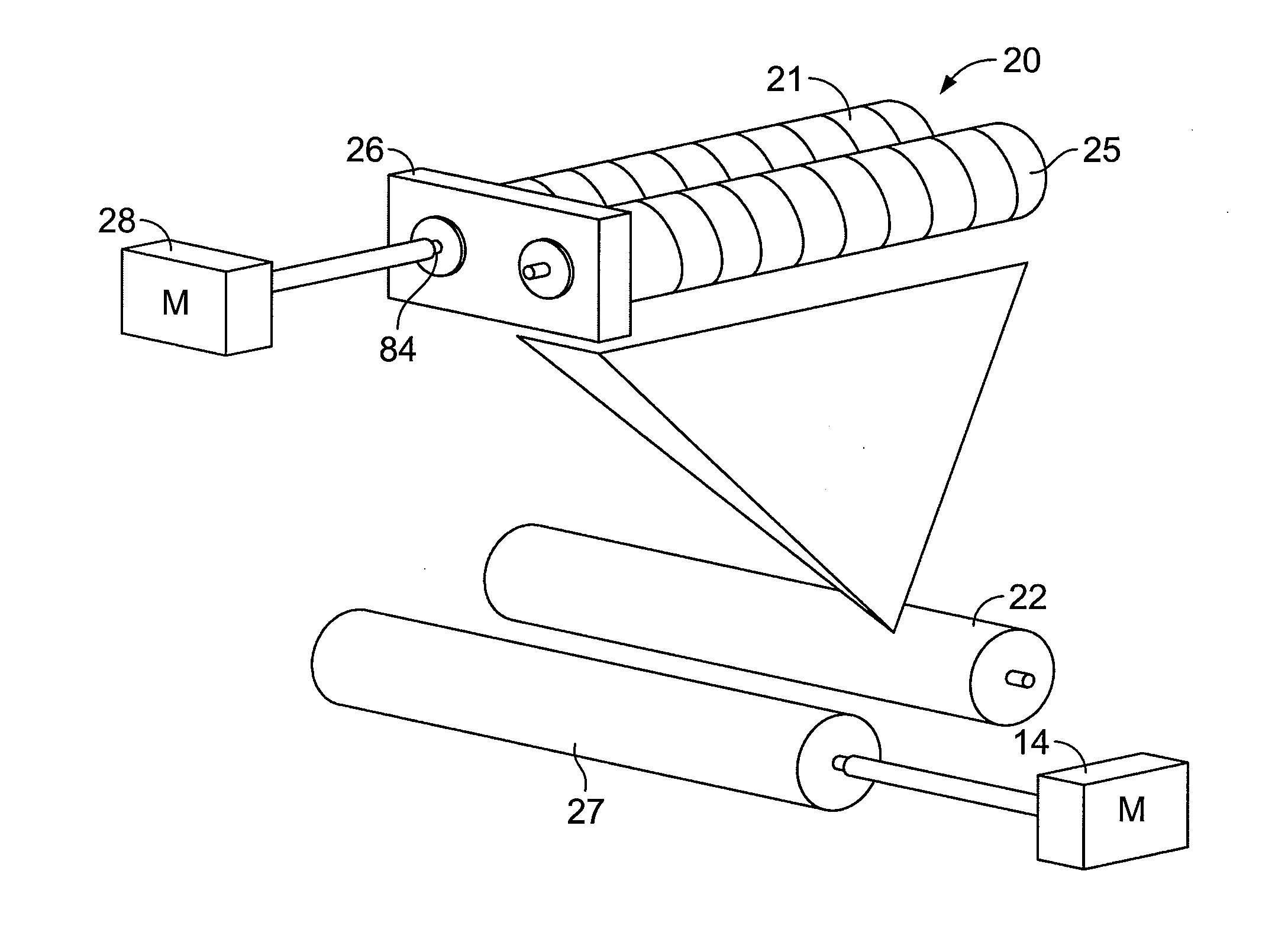
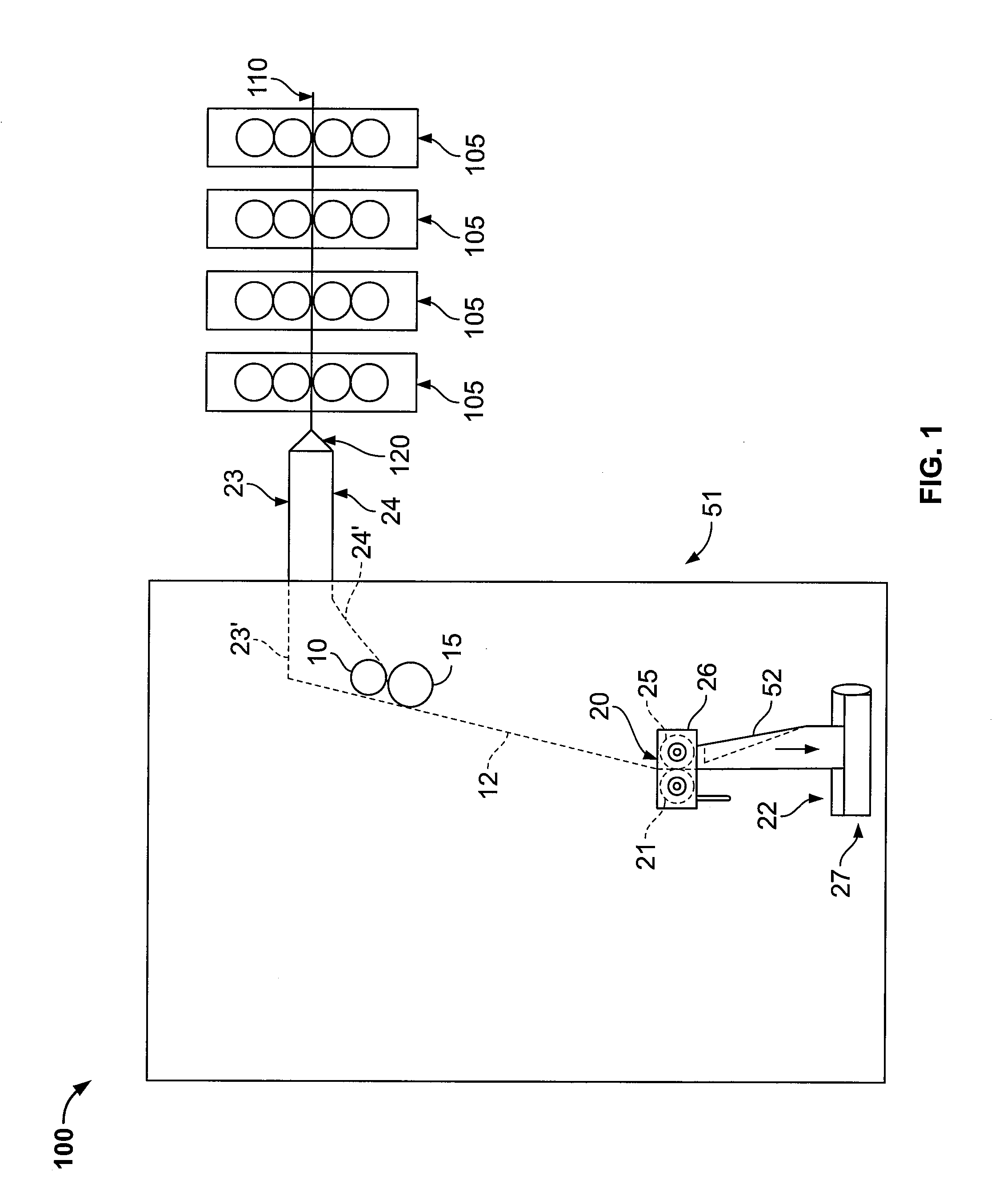
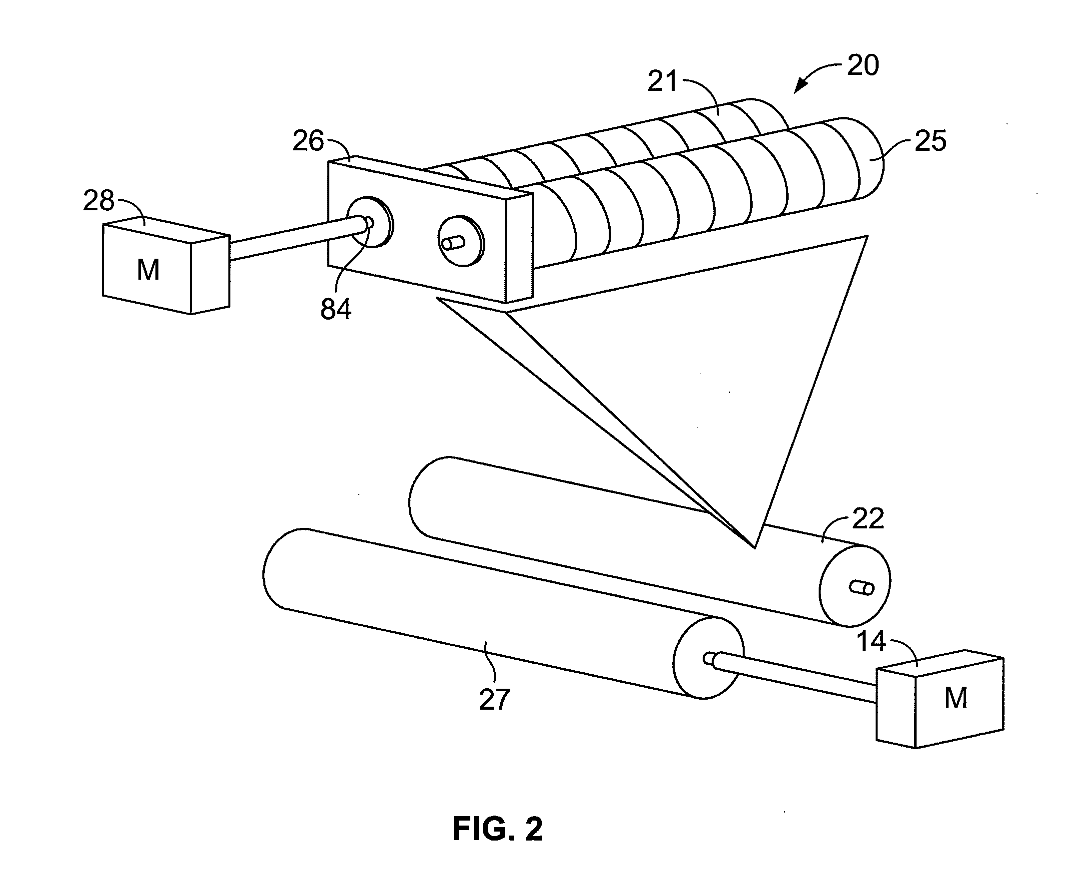
[0013]FIG. 1 shows a schematic view of a web printing press 100 according to the present invention. Printing press 100 includes printing units 105, printing on a web 110. A slitting device 120 slits web 110 into ribbon bundles 23, 24, which enter folder superstructure 51 (shown as 23′ and 24′) and are guided to former 52 by driven lead rolls 10, 15 and RTF 26. As one of skill in the art will readily recognize, if additional ribbons are received by the folder superstructure 51, additional sets of lead rolls will be necessary, one set of lead rolls for each additional ribbon. The ribbons 23′ and 24′ are joined after the driven lead rolls 10, 15 and ribbon bundle 12 consists of ribbons 23′ and 24′. Former 52 longitudinally folds ribbon bundle 12 as ribbon bundle 12 is drawn by driven nip rolls 22, 27, respectively.

[0014]Ribbon bundle 12 is directed towards a ribbon nip entry 20 in RTF 26. RTF 26 includes top of former rolls 21, 25, which may be compressible. Ribbon bundle 12 enters rib...


PUM

PropertyMeasurementUnit
Angleaaaaaaaaaa
Ratioaaaaaaaaaa
Compressibilityaaaaaaaaaa

Abstract

A folder superstructure includes a former, a first top of former roll located upstream of the former and having a compressible outer layer and a second top of former roll forming a nip with the first top of former roll. A method for operating a printing press is also provided.

Description

[0001]The present invention relates generally to folder superstructures for web printing presses, to nip rolls used in multi-ribbon transport, as well as to a method for operating a printing press.BACKGROUND INFORMATION[0002]As described in U.S. Patent Application Publication 2006 / 0157924, hereby incorporated by reference herein, in a web printing press, a web or webs may be printed in various printing units. The webs then may enter a folder superstructure. There, the webs may be slit into ribbons, which are then superimposed to form a ribbon bundle, before passing to a former. The ribbon bundle in the folder superstructure may be drawn over a roller at the top of the former called an RTF by driven nip rolls located after the nose of the former. The ribbon bundle then may pass to a folder where the ribbon bundle is cut into signatures.[0003]The nip rolls may be spring-loaded against each other in an adjustable manner so as to set the pressure or “squeeze.” Nip rolls with urethane or...

Claims


Application Information

Patent Timeline
IPC IPC(8): B41F13/56B65H20/00
CPCB65H45/221B65H2404/563B65H2404/185B65H2404/143
Inventor DOUILLARD, GERALD ROGERDAWLEY, DOUGLAS JOSEPHPERDUE, DANIEL MATTHEWELKINSON, BRIAN ROBERT
Owner GOSS INT AMERICAS
Why Eureka
Try Eureka