Eureka AIR delivers breakthrough ideas for toughest innovation challenges, trusted by R&D personnel around the world.

Wand for an appliance

Inactive Publication Date: 2009-03-19
DYSON TECH LTD
View PDF10 Cites 4 Cited by
  • Summary
  • Abstract
  • Description
  • Claims
  • Application Information

AI Technical Summary

Benefits of technology

[0012]By supporting adjacent tubes at a plurality of discrete points along the common axis, the tubes are held more firmly with respect to one another, and play between the tubes is reduced. This improves the structural strength of the connection between the tubes, together with the perceived quality of the wand as a whole. The support mechanism comprises first and second elements, the first element having a first tapered portion and the second element having a second tapered portion. By providing two separate elements, greater support is achievable. The provision of a moving element further reduces play between the tubes.
[0014]Advantageously, both elements are movable along the common axis with respect to the first and second tubes. By providing such an arrangement, the two elements of the support mechanism are able substantially to eliminate any remaining play between tubes. Therefore, adjacent tubes can be securely held even if manufacturing tolerances or wear during use affect the relative dimensions of the tubes. The first and second elements are able to move to positions in which the first and second tubes are best supported.
[0015]Advantageously, the first and second elements are moveable with respect to one another along the common axis between a maximum and a minimum separation. At least one of the first and second elements may be restrained to prevent the maximum separation from being exceeded. This arrangement prevents the first and second elements from spreading too far apart, which may reduce the ability of the support mechanism to provide support between the two tubes.
[0016]Preferably, the first and second elements are resiliently biased with respect to one another. This may be achieved by means of a coil spring located between the first and second elements. Such an arrangement helps to bias the first and second elements into an optimum support position between the first and second tubes.

Problems solved by technology

Whilst the above type of wand is simple to operate and to manufacture, a two tube arrangement cannot be reduced to a size below a half of its maximum extension.
Therefore, such a wand is bulky and difficult to store.
This type of wand also creates packaging problems for the manufacturer because the box in which the product is supplied has to be of a sufficient size to accommodate the bulky wand.
This bending effect may reduce the structural stability of the wand assembly and the perceived quality of the wand assembly.
However, aluminium is expensive to produce, and increases the weight of a wand assembly.
A wand assembly having more than two tubes requires a smaller connector connecting each of the tubes; otherwise the tubes will not be able to slide inside one another in order to be stored.

Method used


Image

  • Wand for an appliance
  • Wand for an appliance
  • Wand for an appliance

Examples


Embodiment Construction

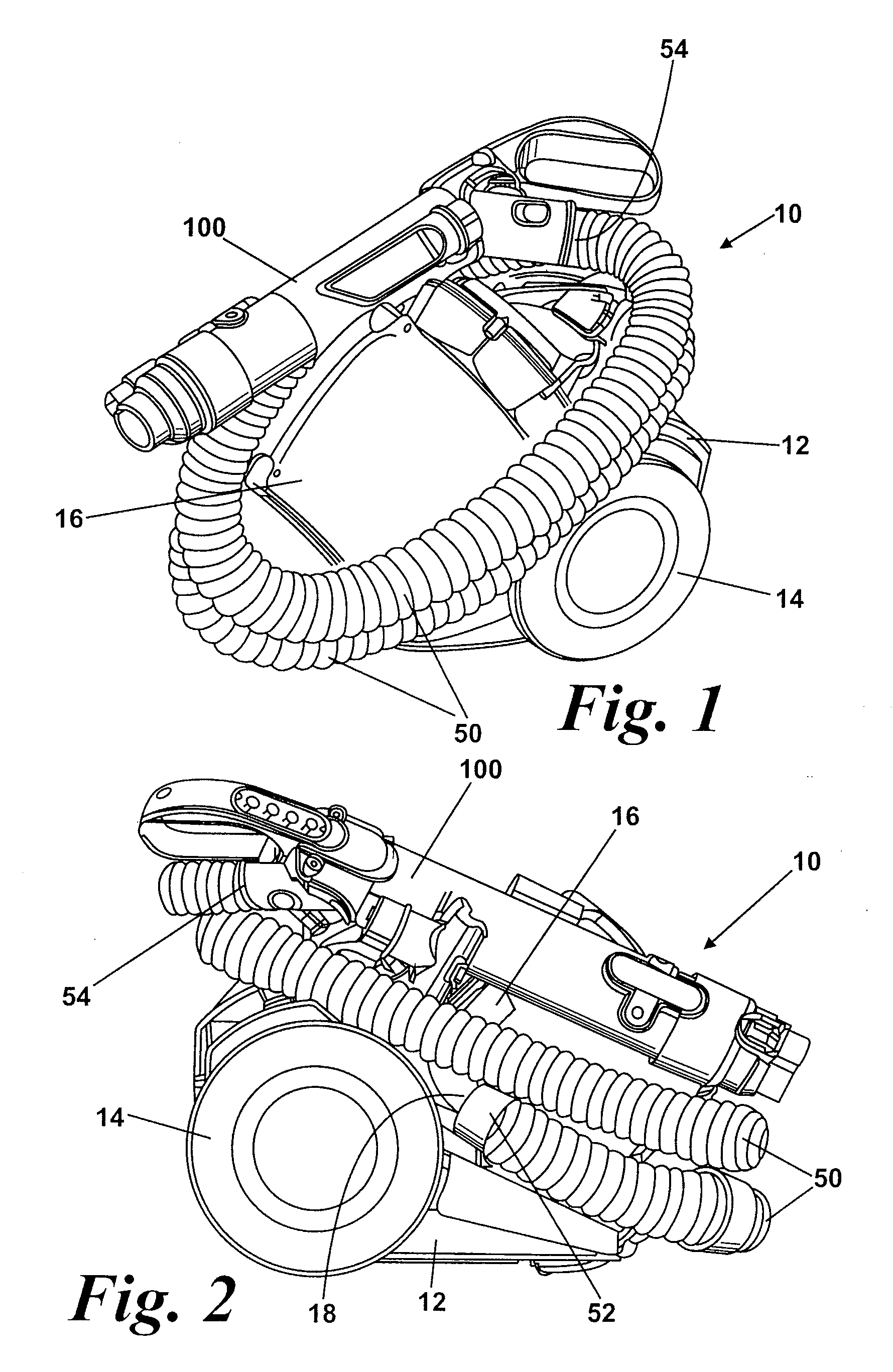
[0031]A vacuum cleaner incorporating a wand according to the invention is shown in FIGS. 1 and 2. The vacuum cleaner 10 has a main body 12 housing a motor and fan unit (not shown) and to which a pair of wheels 14 is attached. The wheels 14 allow the main body 12 of the vacuum cleaner 10 to be manoeuvred across a floor surface. Separating apparatus 16 is releasably attached to the main body 12. In this example, the separating apparatus 16 takes the form of a cyclonic separator. However, other arrangements, for example, a pleated filter or a bag, may be used. The nature of the separating apparatus 16 is not material to the invention.

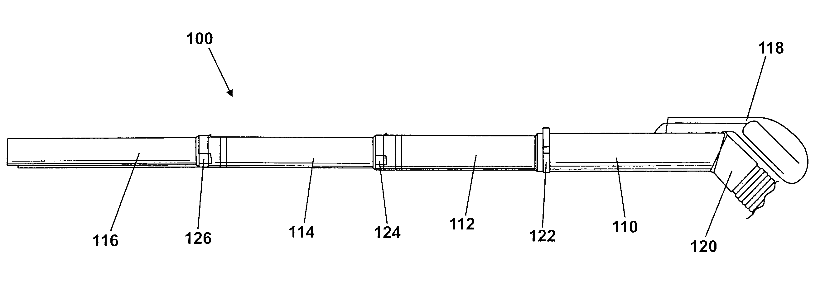
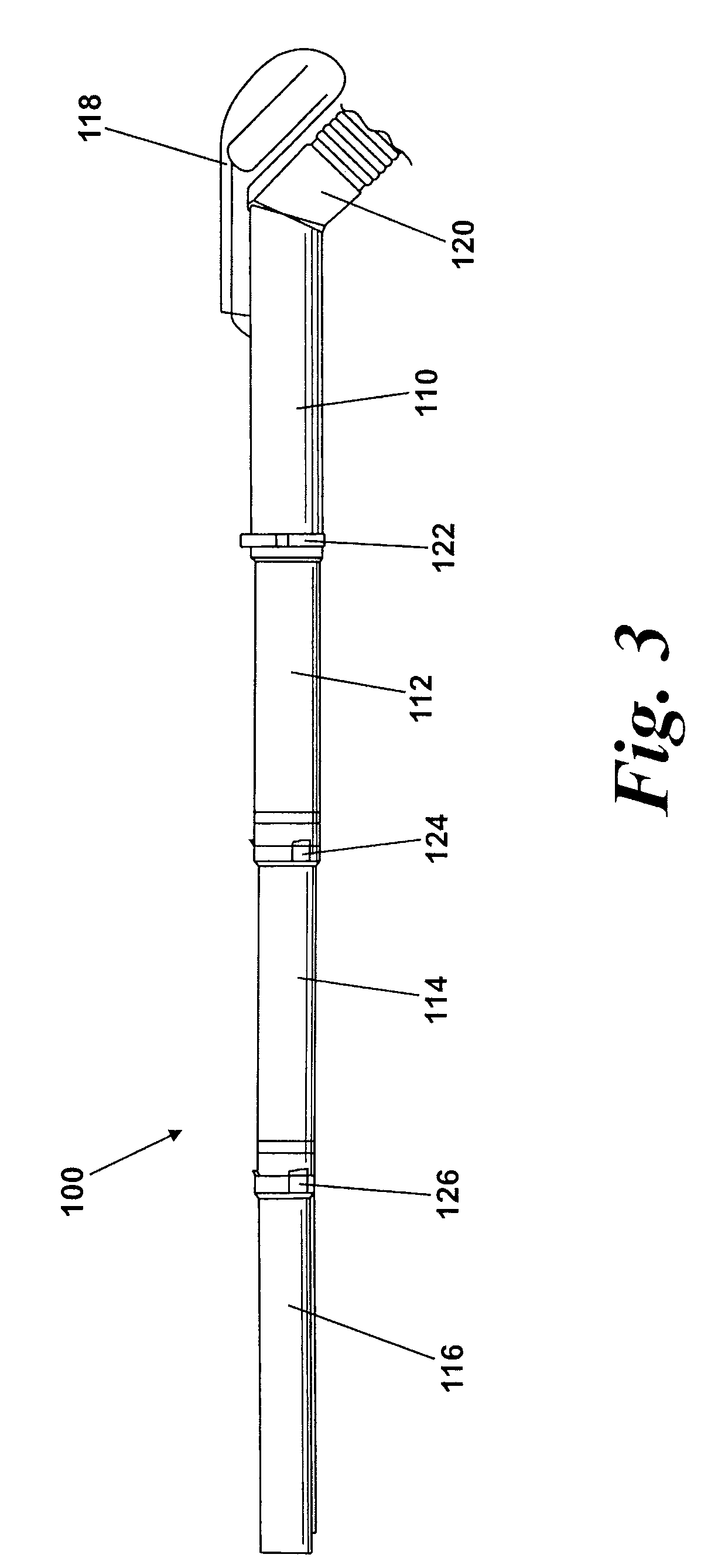
[0032]The separating apparatus 16 has an inlet 18 through which a dirt-laden airflow enters the separating apparatus 16. A hose 50 is connected to the inlet 18 by a first connector 52, which is located at one end portion of the hose. The hose 50 also has a second connector 54 at an opposite end portion to the first connector 52. A wand 100 according to the...


PUM


Abstract

A wand for an appliance includes comprises first and second tubes and a support mechanism, in which the second tube slides telescopically within the first tube along a common axis. The first and second tubes are arranged to be selectively secured to one another in an extended position or to allow movement therebetween and the support mechanism is located between overlapping portions of the tubes. The support mechanism includes tapered portions arranged to provide support between the tubes at separate points along the common axis of the tubes. By supporting adjacent tubes at a plurality of points along the common axis, the tubes are held more firmly with respect to one another. One tapered portion is able to move with respect to the tubes along the common axis, which reduces play between the tubes. The structural strength and quality of the wand are improved.

Description

REFERENCE TO RELATED APPLICATIONS[0001]This application claims the priority of United Kingdom Application No. 0716281.1, filed Aug. 21, 2007, the contents of which are incorporated herein by reference.FIELD OF THE INVENTION[0002]The invention relates to a wand for an appliance such as a vacuum cleaner.BACKGROUND OF THE INVENTION[0003]Cylinder vacuum cleaners are well known and usually comprise a main body and a wand and hose assembly which is attached to the main body. The main body comprises a motor and fan unit for generating an airflow and separating apparatus for separating dirt and dust from the airflow. Commonly, the separating apparatus takes the form of a cyclonic separator or other separating media, such as a bag. The wand and hose assembly comprises a length of flexible hose which is attached to the main body of the vacuum cleaner at one end. A rigid wand is attached to the other end of the hose. The airflow enters the main body through the wand and hose assembly which is ...

Claims


Application Information

Patent Timeline
IPC IPC(8): A47L9/24
CPCA47L9/0036F16B7/105A47L9/244A47L9/0045
Inventor STICKNEY, TIMOTHY NICHOLASSUNDERLAND, DAVID ROBERTGRISTWOOD, MARC LAURENCE EVANS
Owner DYSON TECH LTD
Why Eureka
Eureka Blog
Learn More