Heat insulator suitable for a vehicle exhaust pipe

Inactive Publication Date: 2011-04-21
NAKAGAWA SANGYO
View PDF26 Cites 7 Cited by
  • Summary
  • Abstract
  • Description
  • Claims
  • Application Information

AI Technical Summary

Benefits of technology

[0013]As was described above, a heat insulator for a vehicle exhaust pipe according to the present teachings is capable of exhibiting excellent thermal

Problems solved by technology

However, the above-described known heat insulator still lac

Method used


Image

  • Heat insulator suitable for a vehicle exhaust pipe
  • Heat insulator suitable for a vehicle exhaust pipe
  • Heat insulator suitable for a vehicle exhaust pipe

Examples


Example

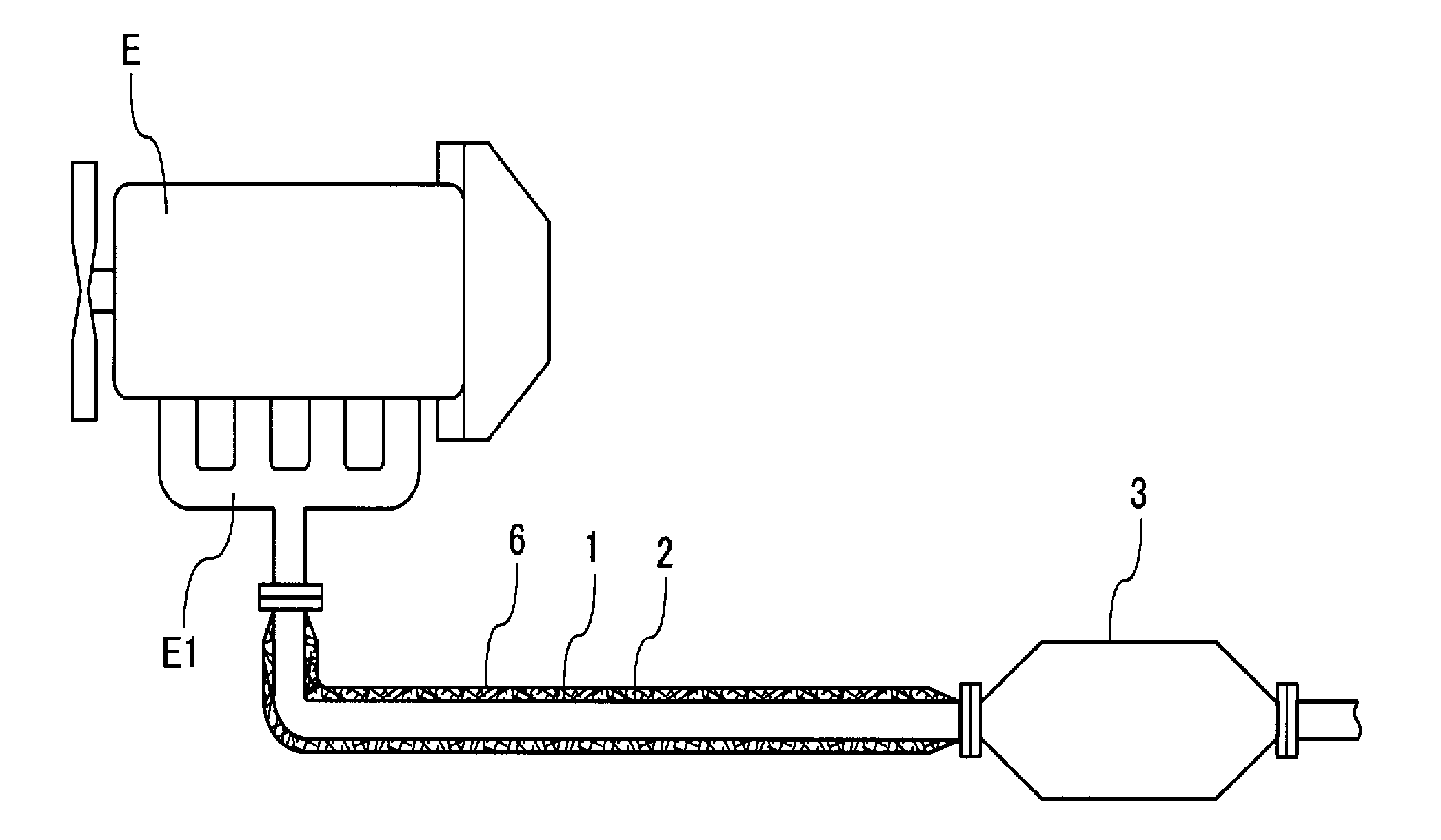
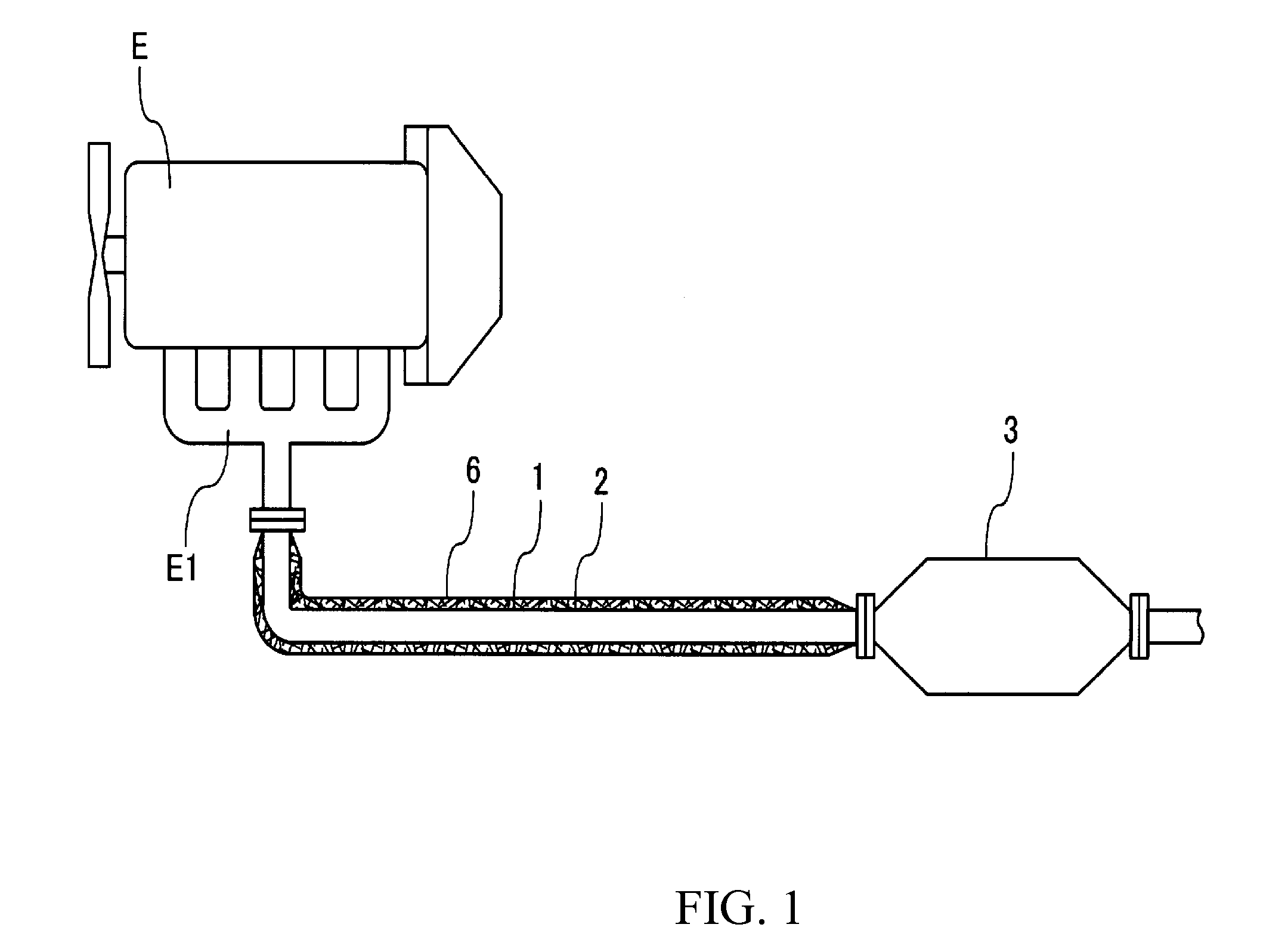
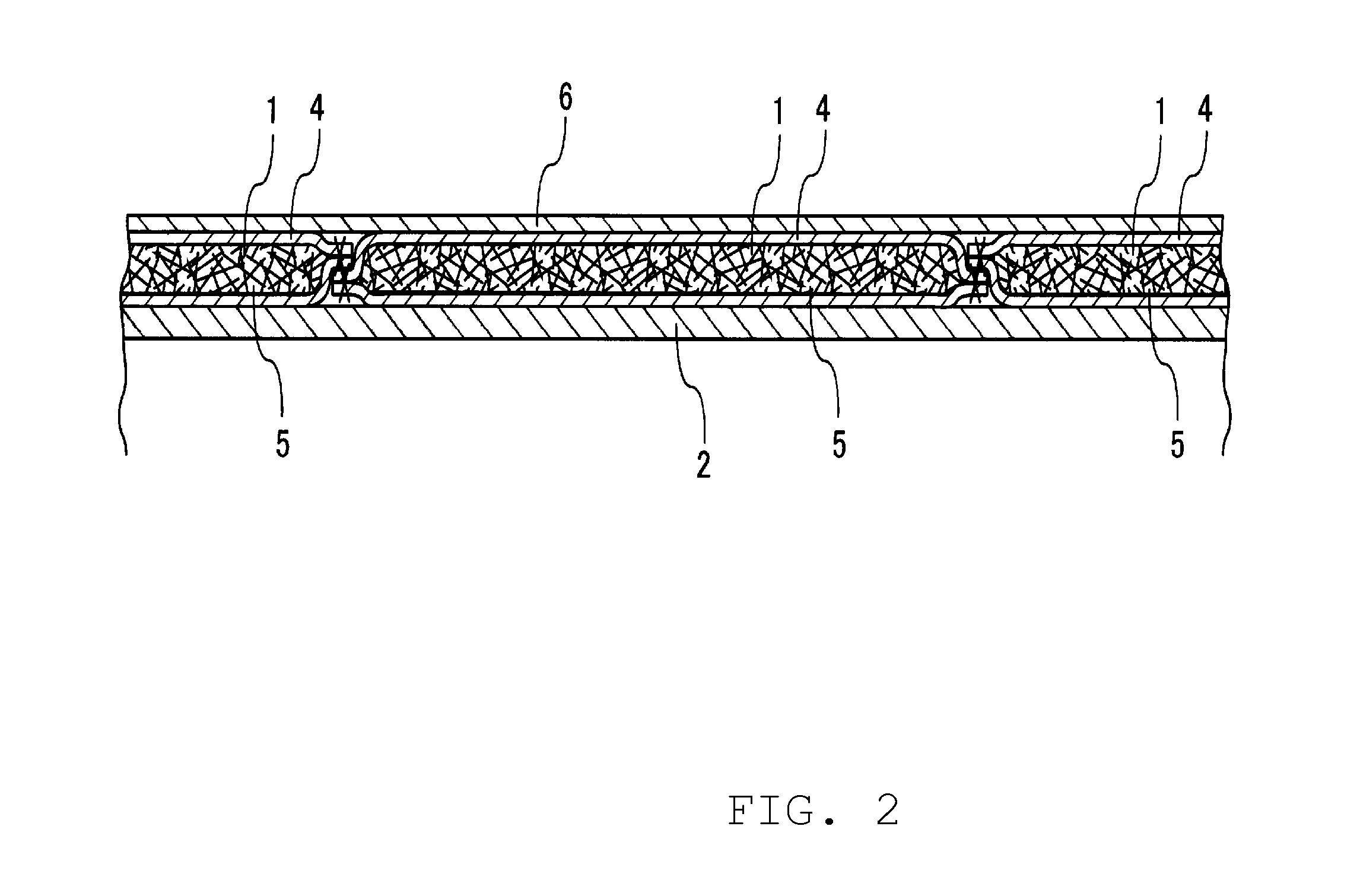
[0018]Referring to FIG. 1, a representative heat insulator 1 according to the present teachings is provided around the outer periphery of a vehicle exhaust pipe 2 which is connected to an exhaust manifold E1 of an engine E so as to extend from an upstream end to an inlet of a catalytic converter 3 provided in a middle portion of the exhaust pipe 2. FIG. 2 shows an enlarged cross-sectional view of the heat insulator 1. Each heat insulator 1 includes a bag member 4 having a certain length and being disposed along the exhaust pipe 2. As shown in FIG. 1, a plurality of heat insulators 1 are wound or wrapped around the outer periphery of the exhaust pipe 2 adjacent to each other in a sufficient number so as to cover the entire outer periphery of the exhaust pipe 2 between the exhaust manifold E1 and the catalytic converter 3. A deformable or bendable sheet-shaped heat insulating material 5 (e.g., a heat insulating mat) having a thickness of 5 mm to 15 mm is inserted into each bag member ...


PUM

PropertyMeasurementUnit
Temperatureaaaaaaaaaa
Lengthaaaaaaaaaa
Lengthaaaaaaaaaa

Abstract

A heat insulator is wound around an outer periphery of a vehicle exhaust pipe. The heat insulator comprises a deformable sheet-shaped heat insulating material hermetically encased in a reduced pressure state in a bag member comprised of heat-resistant metal foil.

Description

CROSS-REFERENCE[0001]This application claims priority to Japanese patent application serial number 2009-240964 filed on 20 Oct. 2009, the contents of which are fully incorporated herein by reference.BACKGROUND OF THE INVENTION[0002]1. Field of the Invention[0003]The present invention relates to a heat insulator, which is suitable for a vehicle exhaust pipe in preferred applications, a vehicle exhaust pipe insulated by the heat insulator as well as methods for manufacturing the heat insulator and the vehicle exhaust pipe insulated by the heat insulator.[0004]2. Description of the Related Art[0005]A catalytic converter for purifying exhaust gas is typically installed in an exhaust pipe of a vehicle and the catalyst used in the catalytic converter is typically activated at a temperature of 300° C. or higher. Thus, after starting up the engine, it is necessary to rapidly increase the temperature of the catalyst to 300° C. or higher in order to promptly start the exhaust gas purification...

Claims


Application Information

Patent Timeline
IPC IPC(8): F16L9/14B21D51/16
CPCF01N13/14Y10T29/49398F01N2510/02F01N13/146
Inventor NAKAGAWA, NORIAKI
Owner NAKAGAWA SANGYO
Why Eureka
Try Eureka