
Chip Carrying Tray

a chip and carrying tray technology, applied in the field of semiconductor carrying devices, can solve the problems of inclination and scratching of solder, and achieve the effect of restricting the slippage of chips

Inactive Publication Date: 2011-04-21
NAN YA TECH
View PDF10 Cites 17 Cited by
  • Summary
  • Abstract
  • Description
  • Claims
  • Application Information

AI Technical Summary

Benefits of technology

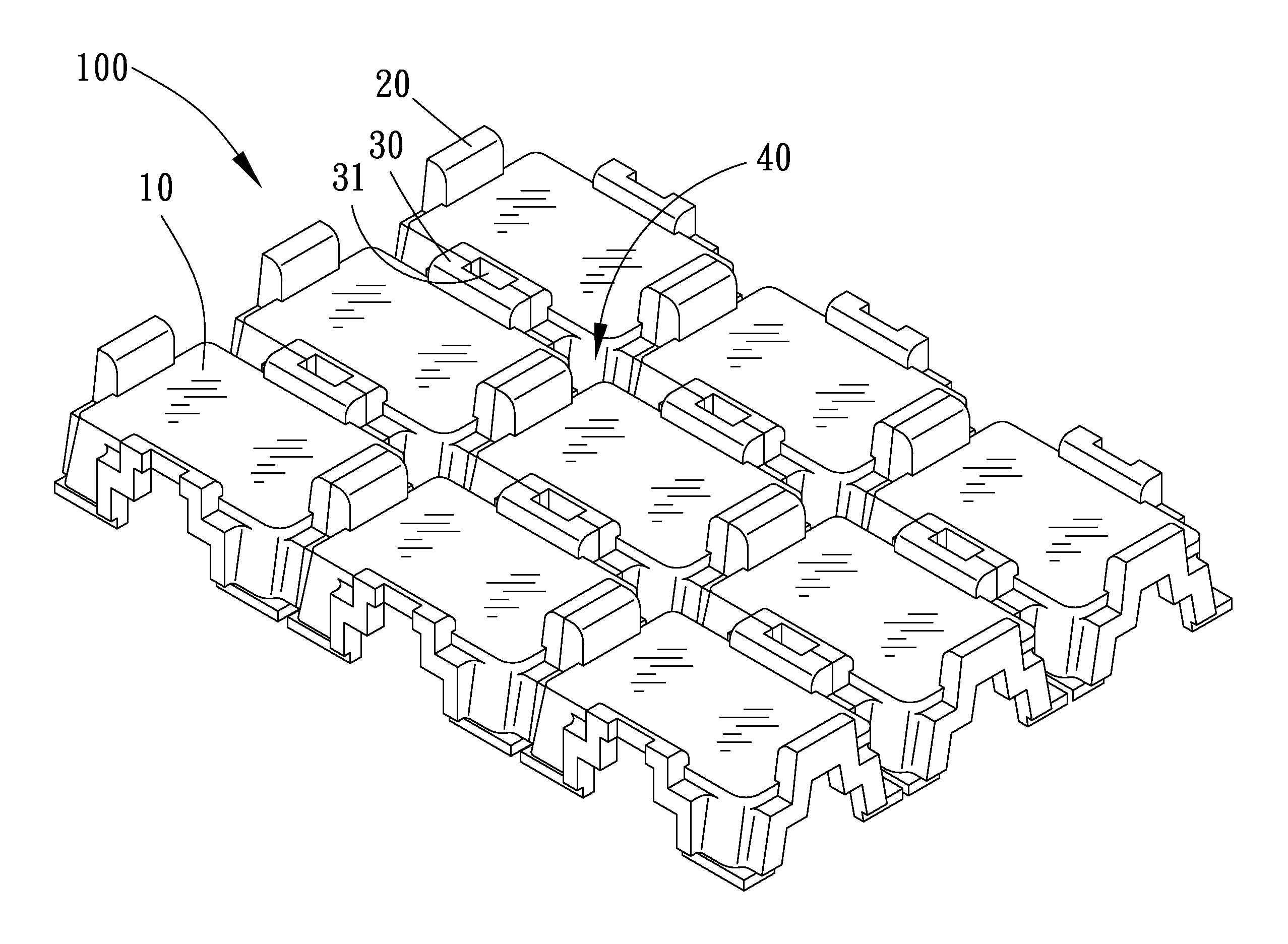
[0007]The primary objective of the present invention is to provide a chip carrying tray which can stably carry the chips and substantially discharge the moisture to keep the chips dry.
[0009]The stopping walls are used to restrict the slippage of the chips, and the through holes of the stopping walls serve as the channels for discharging the moisture of the chip carrying tray to keep the chips dry.

Problems solved by technology

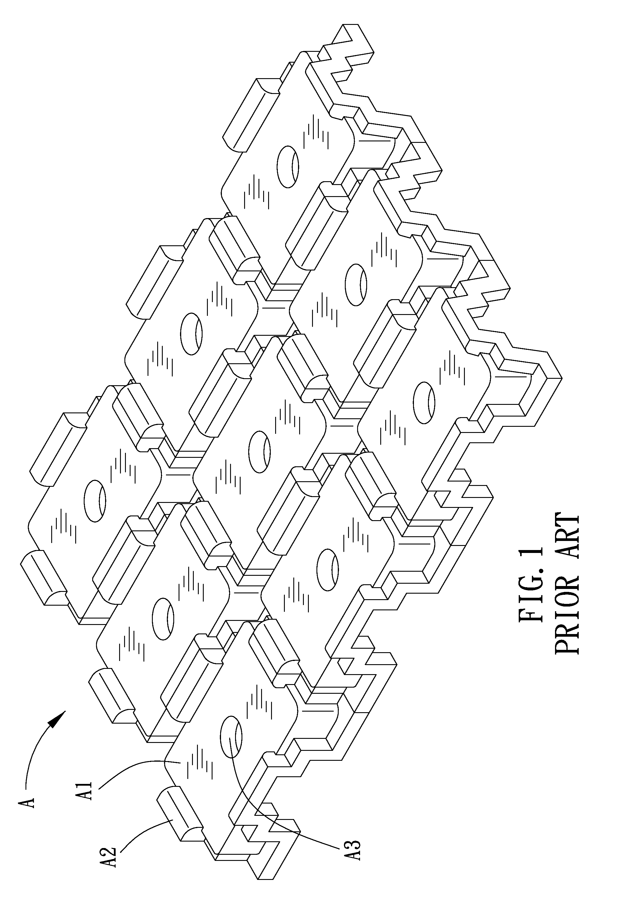
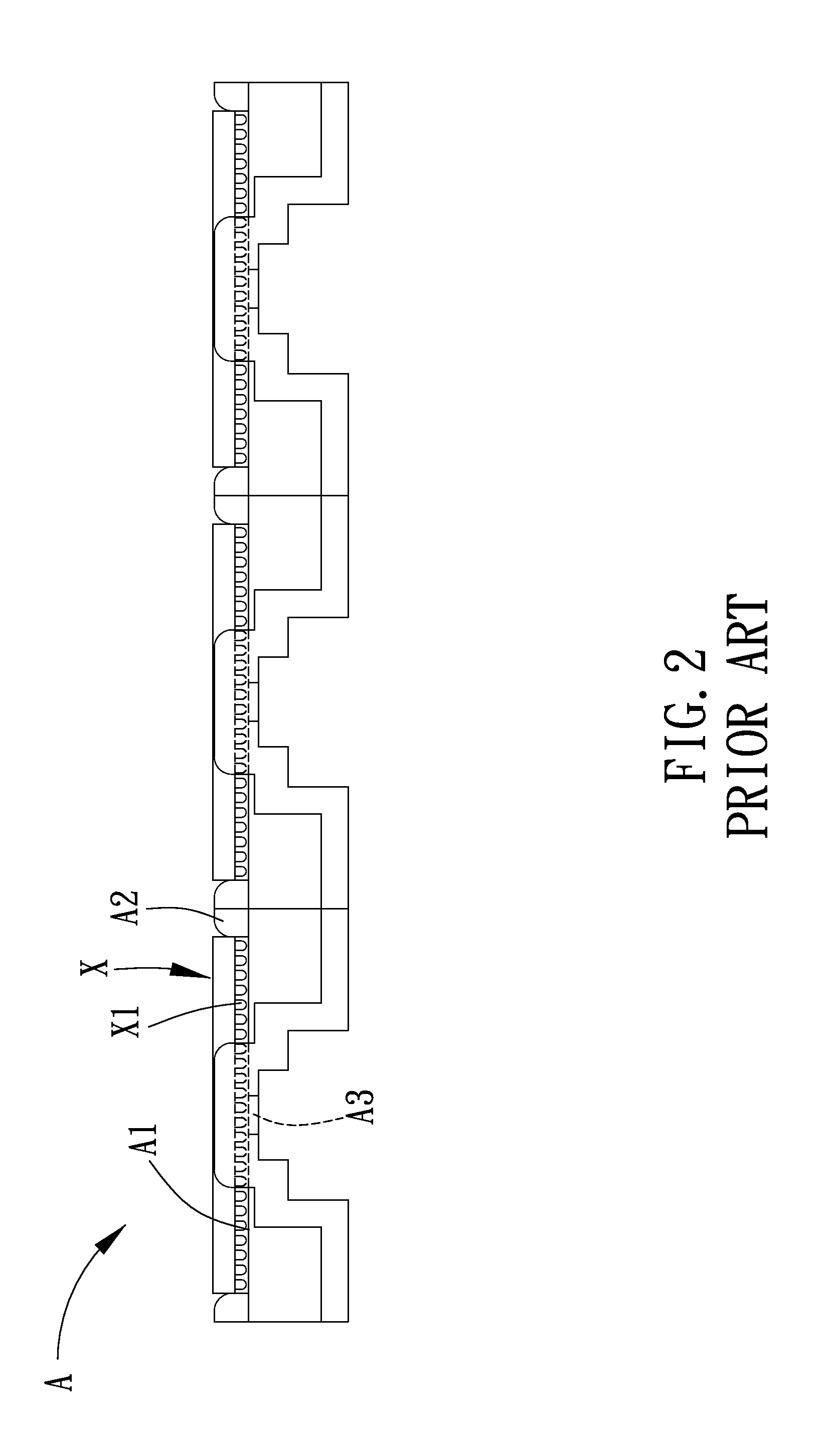
However, the carrying portions are funnel-shaped and non-planar, so that the chips X must be moved with much carefulness in order to be stably placed on the carrying portions, or else they are prone to inclining and scratching the solder balls X1 of the chips X.

Method used


Image

  • Chip Carrying Tray
  • Chip Carrying Tray
  • Chip Carrying Tray

Examples


Embodiment Construction

[0019]The present invention will be clearer from the following description when viewed together with the accompanying drawings, which show, for purpose of illustrations only, the preferred embodiment in accordance with the present invention.

[0020]Referring to FIGS. 4-7, a chip carrying tray 100 in accordance with a preferred embodiment of the present invention comprises plural matrix-arranged carrying portions 10. Each of the carrying portions 10 is rectangular and flat and provided for carrying one chip X. Each of the carrying portions 10 is further provided with two opposite first stopping walls 20 and two opposite second stopping walls 30 around a periphery thereof. The first stopping walls 20 and the second stopping walls 30 are alternately arranged, and the first stopping walls 20 are higher than the respective second stopping walls 30. Each of the second stopping walls 30 is further defined with a through hole 31 in a direction vertical to the carrying portion 10, and each fou...


PUM


Abstract

A chip carrying tray comprises plural rectangular flat carrying portions for carrying plural chips. Each of the carrying portions is provided with stopping walls for restricting the slippage of the chip. The stopping walls are defined with through holes for discharging moisture of the chip carrying tray. By such arrangements, the chip carrying tray can stably carry the chips and substantially keep the chips dry.

Description

BACKGROUND OF THE INVENTION[0001]1. Field of the Invention[0002]The present invention relates to a semiconductor carrying device; and more particularly to a chip carrying tray.[0003]2. Description of the Prior Art[0004]Referring to FIGS. 1-2, a conventional chip carrying tray A comprises plural matrix-arranged carrying portions A1. Each of the carrying portions A1 includes four stopping walls A2 around a periphery thereof. Chips X are placed in the respective carrying portions A1 and restricted by the stopping walls A2. Further, each of the carrying portions A1 is defined with a through hole A3 for discharge of moisture from the chip carrying tray A to keep the chips X in the chip carrying tray A dry. However, each of the chips X includes plural solder balls X1 on a bottom thereof, when the chips X are placed on the respective carrying portions A1, the solder balls X1 will be brought into contact with the through holes A3 of the carrying portions A1, and thus the edges of the throug...

Claims


Application Information

Patent Timeline
IPC IPC(8): B65D85/00
CPCH01L21/67333
Inventor LO, YU-NAN
Owner NAN YA TECH
Learn More