Method for producing an elastomer membrane and elastomer membrane

a technology of elastomer membrane and elastomer membrane, which is applied in the direction of engine diaphragms, applications, other domestic articles, etc., can solve the problems of electronic data carriers slipping towards the edge of mold cavities and damage to electronic data carriers

Inactive Publication Date: 2018-10-11
GEBRUDER MULLER APPARATEBAU GMBH & CO KG
View PDF0 Cites 0 Cited by
  • Summary
  • Abstract
  • Description
  • Claims
  • Application Information

AI Technical Summary

Benefits of technology

[0007]The method comprises arranging an electronic data carrier between two layers in a predetermined position, the electronic data carrier being connected at least temporarily to a positioning aid. The method further comprises compression molding the two layers with the electronic data carrier arranged therebetween, the positioning aid limiting slippage of the electronic data carrier out of the predetermined position during the compression molding.
[0008]The proposed positioning aid results in the tolerances when arranging the electronic data carrier within the elastomer membrane being reduced. In other words, over a range of similar membranes, the electronic data carrier is positioned substantially at the same point within the membrane. Advantageously, waste during production can thus be minimized and the reading accuracy of the electronic data carrier is increased by ensuring the predetermined position.

Problems solved by technology

When vulcanizing electronic data carriers in between coats or layers of an elastomer membrane, there is the problem that the electronic data carrier can slip towards the edge of the mold cavity during the vulcanizing process.
As a result of this, the electronic data carrier may be damaged in the further production process or after the membrane has been dispatched for delivery.

Method used


Image

  • Method for producing an elastomer membrane and elastomer membrane
  • Method for producing an elastomer membrane and elastomer membrane
  • Method for producing an elastomer membrane and elastomer membrane

Examples


Embodiment Construction

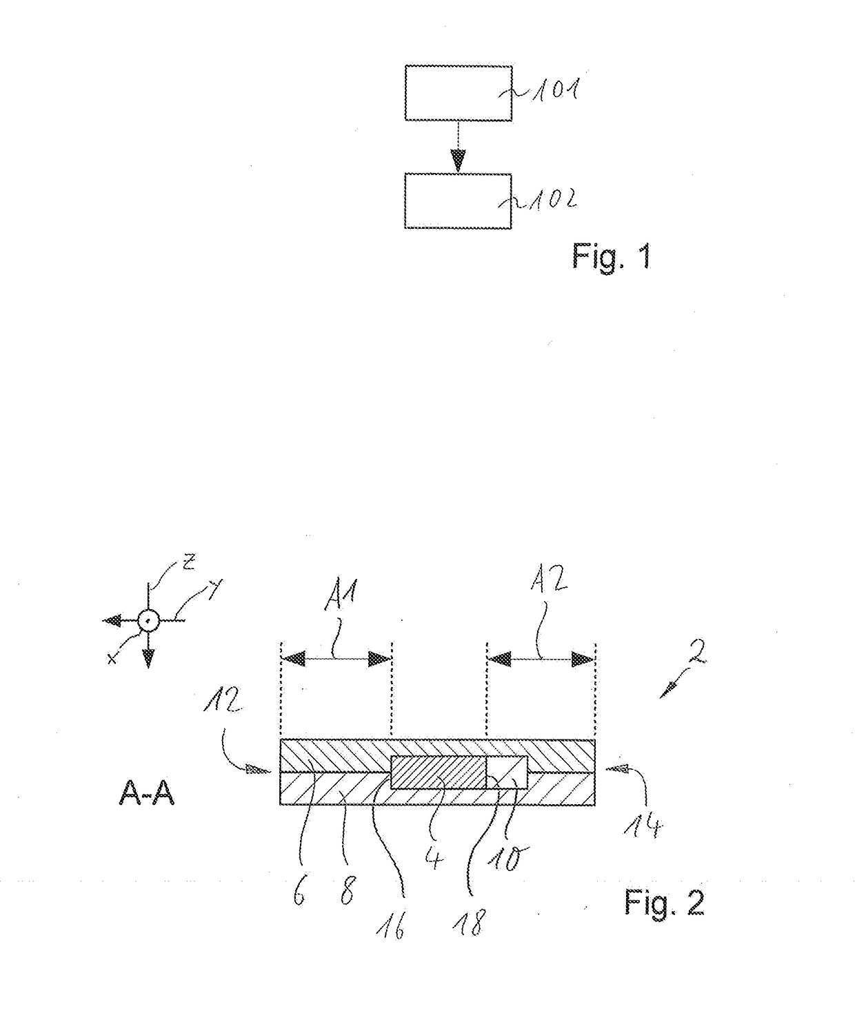
[0029]FIG. 1 shows a schematic flow chart of a method for producing an elastomer membrane. In a first step 101, an electronic data carrier is arranged at least temporarily between two layers in a predetermined position. The electronic data carrier is connected to a positioning aid. In a second step 102, the two layers are compression molded with the electronic data carrier arranged therebetween, the positioning aid limiting slippage of the electronic data carrier out of the predetermined position during the compression molding.

[0030]The two aforementioned layers are blank layers which are used as a starting material for vulcanizing and thus producing the elastomer membrane. The two layers are cut out of raw-rubber sheets following a pattern.

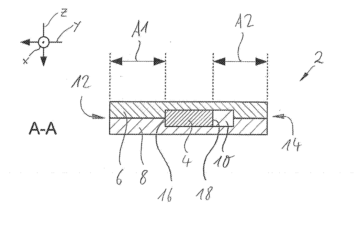
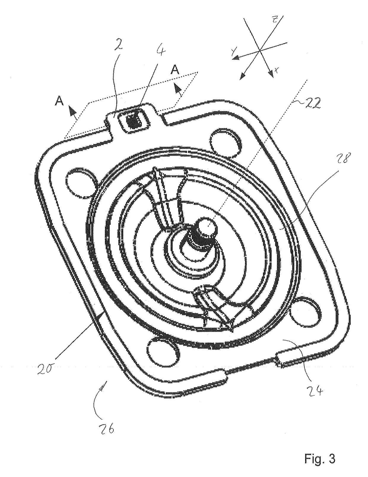
[0031]FIG. 2 shows a schematic cross section A-A from the following figure, FIG. 3. The cross section A-A shows a tab 2 of the elastomer membrane, in which the electronic data carrier 4 is arranged between two layers 6 and 8. After vulcanization ...


PUM

PropertyMeasurementUnit
temperatureaaaaaaaaaa
lengthaaaaaaaaaa

Abstract

A method for producing an elastomer membrane is proposed. The method includes the step of arranging an electronic data carrier between two layers in a predetermined position, wherein the electronic data carrier is connected at least temporarily to a positioning aid. Compression molding the two layers with the electronic data carrier arranged therebetween is also provided, wherein the positioning aid limits slippage of the electronic data carrier out of the predetermined position during the compression molding.

Description

CROSS-REFERENCE TO RELATED APPLICATIONS[0001]This application relates and claims priority to European Application No. EP 17305428.9-1706 filed Apr. 10, 2017, the entire disclosure of which is incorporated herein by reference.BACKGROUND OF THE INVENTION[0002]The invention relates to a method for producing an elastomer membrane and to an elastomer membrane.[0003]When vulcanizing electronic data carriers in between coats or layers of an elastomer membrane, there is the problem that the electronic data carrier can slip towards the edge of the mold cavity during the vulcanizing process. As a result of this, the electronic data carrier may be damaged in the further production process or after the membrane has been dispatched for delivery.[0004]DE 10 2013 214 84 A1 discloses a membrane provided with a membrane surface, which is a functional portion of the membrane. A tab is provided in which an electronic data carrier is arranged. The tab comprises an upper and a lower coat. The data carri...

Claims


Application Information

Patent Timeline
Patent Type & Authority Applications(United States)
IPC IPC(8): B29C43/20B29C69/00
CPCB29C43/203B29C69/001B29K2913/00B29L2031/755B29L2031/34B29C51/12B29C51/30B29C51/428B29C51/46B32B37/185B32B38/1841F16J3/02B32B2519/02
Inventor MUELLER, GERT
Owner GEBRUDER MULLER APPARATEBAU GMBH & CO KG
Why Eureka
Try Eureka