Cable mounting member, cable mounting member with cable and connector

a technology of cable mounting and connector, which is applied in the direction of coupling device details, coupling device connections, cables with twisted pairs/quadruples, etc., can solve the problems of changing affecting the transmission performance, and reducing the holding force of the cable. , the effect of suppressing the deterioration of the transmission performance due to the change of the impedance of the cabl

Active Publication Date: 2019-11-12
AUTONETWORKS TECH LTD +2
View PDF7 Cites 1 Cited by
  • Summary
  • Abstract
  • Description
  • Claims
  • Application Information

AI Technical Summary

Benefits of technology

[0006]According to this configuration, the first and second holding portions hold the cable by being held in contact with the outer peripheral surface of the insulation coating at different positions in the direction along the axial direction of the cable. A pulling force on the cable causes the first coupling to deflect and deform so that the cable between the first and second holding portions can bend locally. This causes a frictional force between the core and the insulation coating to increase at a position where the cable is bent and makes the insulation coating difficult to slip relative to the core. Thus, a cable holding force by the cable mounting member remains high.
[0007]A terminal that is crimped to the cable with a strong force to restrict slippage of the insulation coating relative to the core may change an impedance of the cable and may affect transmission performance. However, the cable of this disclosure is bent locally and can be held even if the terminal is not crimped to the cable with a strong force. Thus, the deterioration of transmission performance due to an impedance change of the cable can be suppressed.
[0008]The cable mounting member may further have a third holding portion spaced from the first and second holding portions along the axial direction of the cable via a second slit for holding the cable by contacting the outer peripheral surface of the insulation coating. A deflectable and deformable second coupling may be in a part between the second and third holding portions where the second slit is absent and may couple the second and third holding portions. The second coupling is offset from the first coupling in a circumferential direction of the cable. With this arrangement, a force to pull the cable will deflect the first and second couplings so that the cable can bend locally at plural positions. Thus, the insulation coating is less likely to slip relative to the core, and a reduction of a cable holding force by the cable mounting member is suppressed further.
[0009]The cable mounting member may further include two barrel pieces that define the first holding portion, the second holding portion and the first coupling. The barrel pieces include an overlap in which a tip side of one barrel piece overlaps on a tip side of the other barrel piece, and the first coupling may be provided in the overlap. With this arrangement, the strength of the first coupling is enhanced by a thickness of the overlap so that the width of the first coupling can be reduced and the first coupling can be made flexible while enhancing the strength thereof.
[0010]The cable may be an unshielded twist pair cable (hereafter a UTP cable) including a twisted pair cable as the core and the insulation coating collectively surrounding the twisted pair cable. The UTP cable has no shield layer. Thus, friction between the twisted pair cable and the insulation coating is small as compared to an STP cable or the like having a shield layer, and the UTP cable has a property that the insulation coating easily slips relative to the twisted pair cable. Thus, a frictional force between the twisted pair cable and the insulation coating can be increased by locally bending the UTP cable having such a property. Thus, the insulation coating becomes less likely to slip relative to the core and a reduction of the cable holding force by the cable mounting member can be suppressed.

Problems solved by technology

A pulling force may act on the cable having the crimping terminal crimped thereto and may cause the insulation coating to elongate and slip relative to the core inside.
This causes a frictional force between the core and the insulation coating to increase at a position where the cable is bent and makes the insulation coating difficult to slip relative to the core.
A terminal that is crimped to the cable with a strong force to restrict slippage of the insulation coating relative to the core may change an impedance of the cable and may affect transmission performance.

Method used


Image

  • Cable mounting member, cable mounting member with cable and connector
  • Cable mounting member, cable mounting member with cable and connector
  • Cable mounting member, cable mounting member with cable and connector

Examples


first embodiment

[0039]A first embodiment is described with reference to FIGS. 1 to 19. A connector 10 (FIG. 17) of this embodiment is installed in a vehicle such as an electric or hybrid vehicle and can be disposed in a wired communication path between an in-vehicle electric component (car navigation system, ETC (Electronic Toll Collection System), monitor or the like) in the vehicle and an external device (camera or the like) or between in-vehicle electric components. The connector 10 can be arranged in an arbitrary orientation, but the following description is made with an X direction as a forward direction, a Y direction as a rightward direction and a Z direction as an upward direction.

(Connector 10)

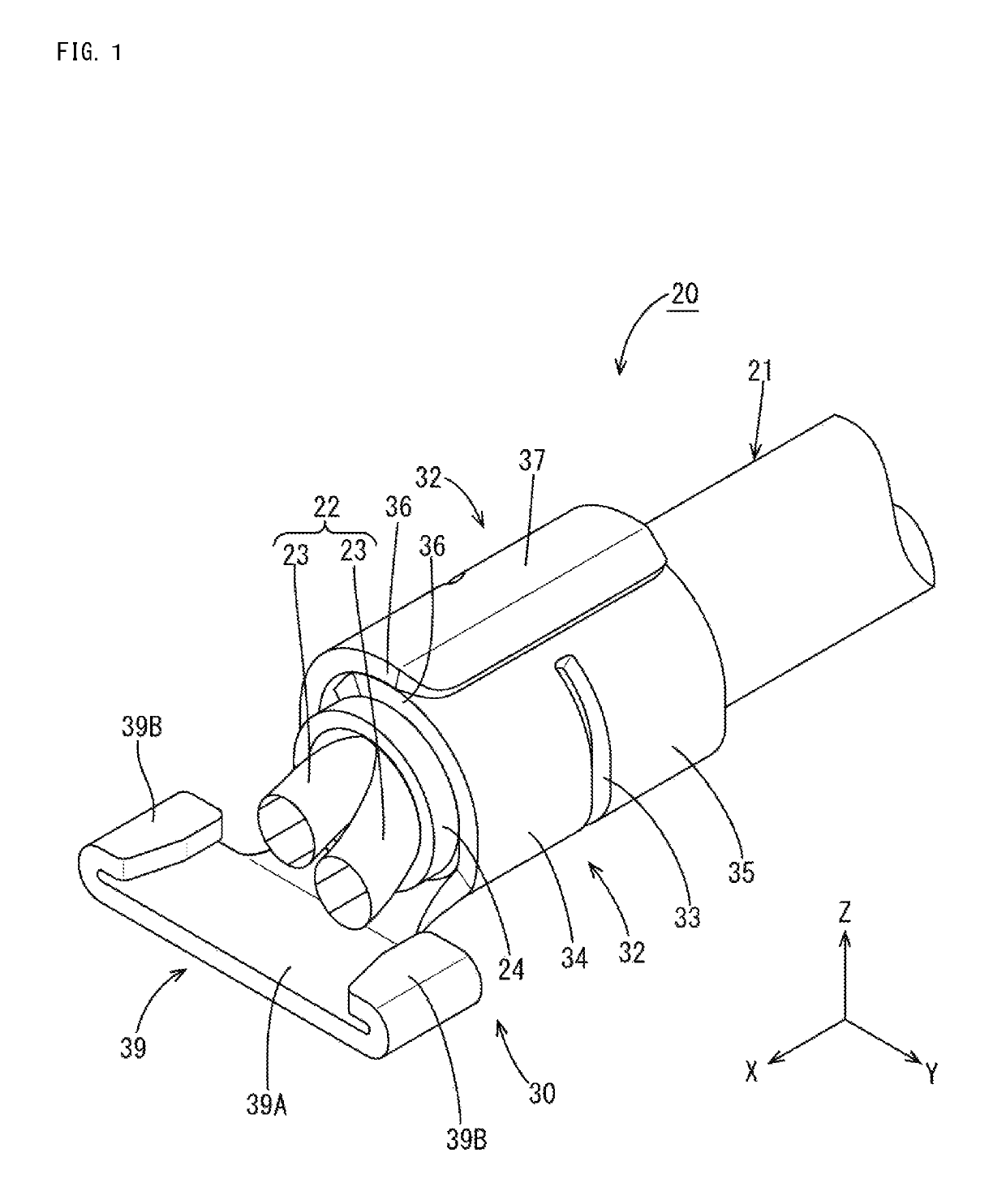
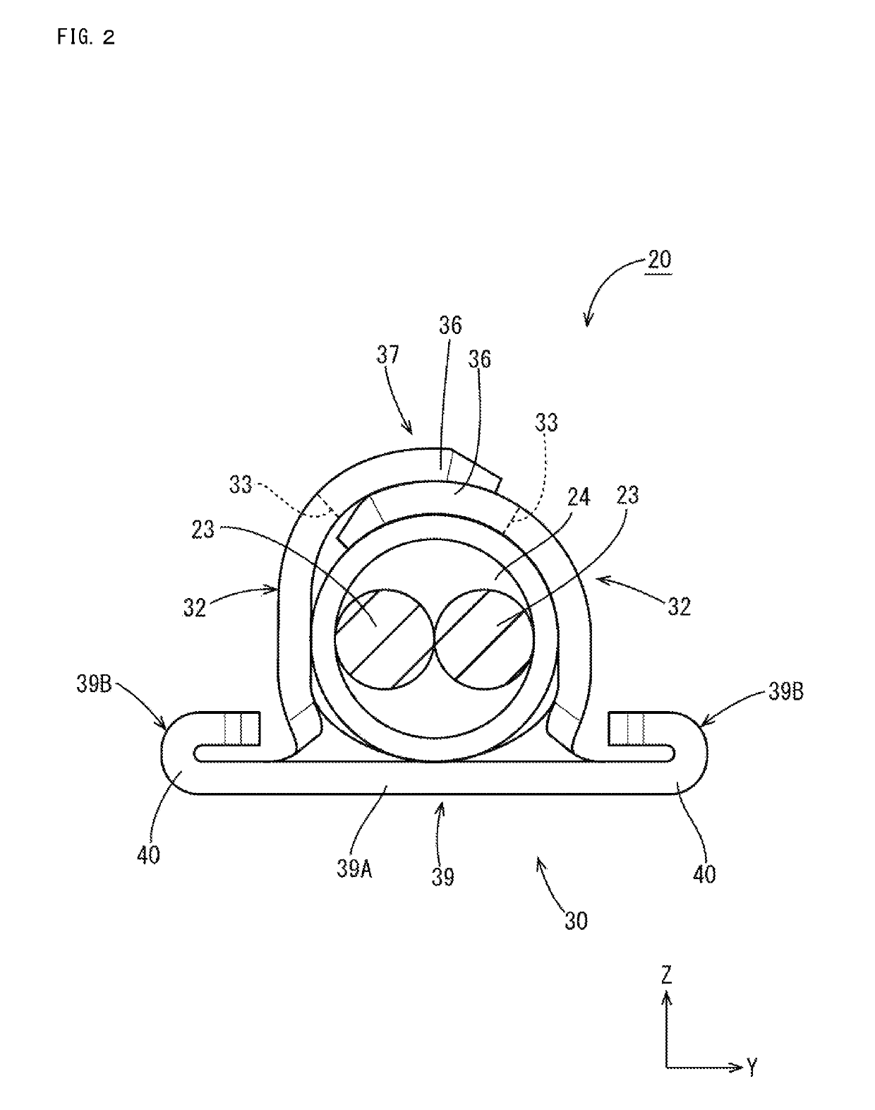
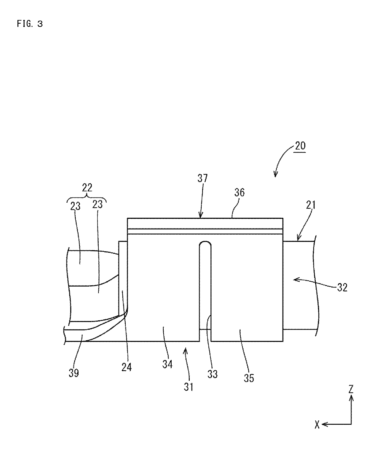
[0040]As shown in FIG. 9, the connector 10 includes a cable mounting member with cable 20 formed by mounting a cable mounting member 30 on a cable 21, and a housing 50 for accommodating the cable mounting member 30.

(Cable Mounting Member with Cable 20)

[0041]As shown in FIG. 1, the cable mounting memb...

third embodiment

[0060]A third embodiment is described with reference to FIGS. 22 to 26. In the following description, the same components as in the above embodiments are denoted by the same reference signs and not described.

[0061]A bottom plate portion and a pair of barrel pieces of a cable mounting member 80 of the third embodiment include a first holding portion 34 for holding a cable 21 by being held in contact with the outer peripheral surface of an insulation coating 24 of the cable 21, a second holding portion 35 for holding the cable 21 by being held in contact with the outer peripheral surface of the insulation coating 24 of the cable 21 at a position different from the first holding portion 34 in a direction along an axial direction of the cable 21, and a third holding portion 81 for holding the cable 21 by being held in contact with the outer peripheral surface of the insulation coating 24 of the cable 21 at a position different from the first and second holding portions 34, 35 in the dir...


PUM

PropertyMeasurementUnit
angleaaaaaaaaaa
anglesaaaaaaaaaa
areasaaaaaaaaaa

Abstract

A cable mounting member (30) to be mounted on a cable (21) including cores (23) and an insulation coating (24) surrounding the cores (23) includes a first holding portion (34) for holding the cable (21) by being held in contact with an outer peripheral surface of the insulation coating (24), a second holding portion (35) provided at a position different from the first holding portion (34) in a direction along an axial direction of the cable (21) via a first slit (33) for holding the cable (21) by being held in contact with the outer peripheral surface of the insulation coating (24), and deflectable and deformable first couplings (37) provided in parts between the first and second holding portions (34, 35) where the first slit (33) is absent and coupling the first and second holding portions (34, 35).

Description

BACKGROUNDField of the Invention[0001]The invention relates to a cable mounting member.Description of the Related Art[0002]Japanese Unexamined Patent Publication No. 2012-155892 describes a crimping terminal to be crimped to a cable that includes a core and an insulation coating surrounding the core. This crimping terminal includes a first standing portion of an overlap type and a second standing portion of a non-overlap type. The first and second standing portions are crimped respectively to the insulation coating of the cable.[0003]A pulling force may act on the cable having the crimping terminal crimped thereto and may cause the insulation coating to elongate and slip relative to the core inside. However, a cable holding force by the crimping terminal of Japanese Unexamined Patent Publication No. 2012-155892 may be reduced if the insulation coating slips relative to the core.[0004]The cable mounting member described in this specification was completed based on the above situation...

Claims


Application Information

Patent Timeline
Patent Type & Authority Patents(United States)
IPC IPC(8): H01R4/18H01R13/58H01B11/02
CPCH01R13/5808H01R4/185H01B11/02H01R2201/26
Inventor HAMADA, KAZUAKIMIYAMOTO, KENJI
Owner AUTONETWORKS TECH LTD
Why Eureka
Try Eureka