Power roller bearing for toroidal-type continuously variable transmission

a technology of power roller bearing and transmission shaft, which is applied in the direction of shaft and bearing, friction gearing, gearing, etc., can solve the problems of reducing the efficiency of the toroidal-type continuously variable transmission shaft, and achieve the effect of restricting slippage and preventing the efficiency of the power roller bearing from being lowered

Inactive Publication Date: 2006-05-02
NSK LTD
View PDF15 Cites 2 Cited by
  • Summary
  • Abstract
  • Description
  • Claims
  • Application Information

AI Technical Summary

Benefits of technology

[0013]In view of the above circumstances of the related art, it is an object of the invention to provide a power roller bearing which can restrict the slippage between balls and rolling surfaces to thereby be able to prevent the efficiency of the power roller bearing from being lowered.
[0014]In attaining the above object, according to the invention, there is provided a power roller bearing for rotatably supporting a power roller of a toroidal-type continuously variable transmission, comprising: an inner ring; an outer ring; a plurality of balls interposed between the inner and outer rings; and, a retainer for holding the balls therein, wherein the retainer includes a plurality of pockets for storing the balls therein at equi-distant positions in the peripheral direction of the retainer, and the inner peripheral portions of the pockets are respectively formed of such elastic material that, when the power roller rotates, allows the balls to shift from the equi-distant positions.
[0016]Since, when the power roller rotates, for the above-mentioned reason, there are produced the orbital speed differences between the balls, the balls are going to roll shifted from their respective equi-distant positions. The retainer, which is used in the power roller bearing according to the invention, due to its elasticity, allows the balls to roll shifted from their respective equi-distant positions. Thus, the reactive forces, which are given to the balls from the retainer when they are contacted with each other, are small. Therefore, the shifting amounts of the balls can be made to approach the ideal shifting amounts, thereby being able to restrict slippage between the balls and rolling surfaces.
[0017]In the present invention, preferably, the inside diameter of each of the pockets may be larger than the outside diameter of each of the balls, the inside diameter of the opening of each pocket may be smaller than the outside diameter of each ball, and the retainer may have such elasticity that allows the opening to spread more than the outside diameter of the ball. In this case, the balls can be easily inserted into their associated pockets. This makes it possible to prevent the balls incorporated into the retainer from slipping out of the retainer.

Problems solved by technology

That is, the respective balls 22 are caused to slide on the rolling surface by the amount of M, which reduces the efficiency of the toroidal-type continuously variable transmission.

Method used


Image

  • Power roller bearing for toroidal-type continuously variable transmission
  • Power roller bearing for toroidal-type continuously variable transmission
  • Power roller bearing for toroidal-type continuously variable transmission

Examples


first embodiment

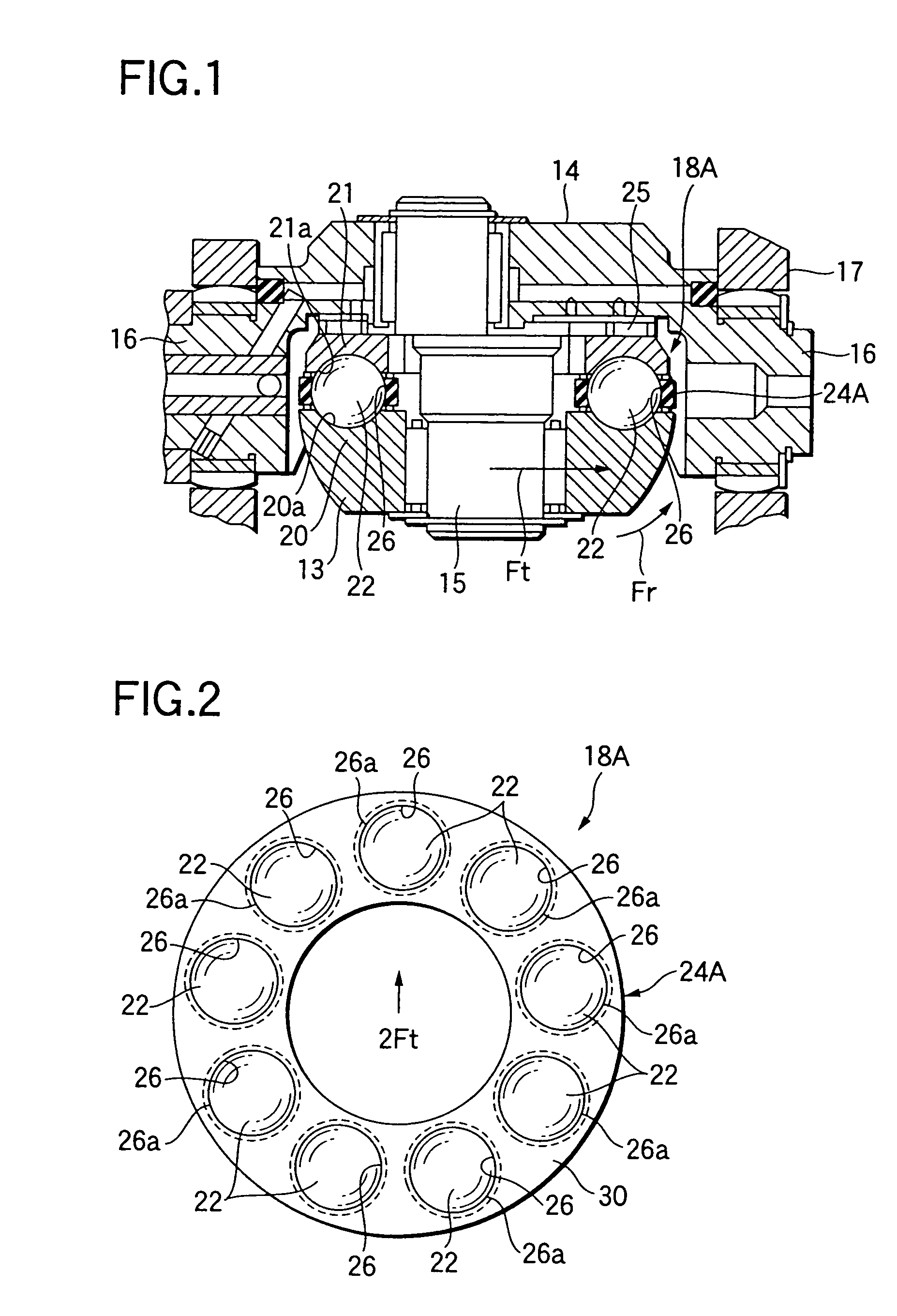
[0036]Now, description will be given below of a power roller bearing 18A according to the invention with reference to FIGS. 1 to 4.

[0037]As shown in FIG. 1, between a power roller 13 and a trunnion 14, there is interposed a power roller bearing 18A. The power roller 13, as in the half-toroidal-type continuously variable transmission shown in FIG. 9, is interposed between an input disk and an output disk. The power roller 13 rotates about a displacement shaft 15 disposed on the trunnion 14. The trunnion 14 is supported by a pair of trunnion shafts 16 so as to be swung with respect to a support body 17.

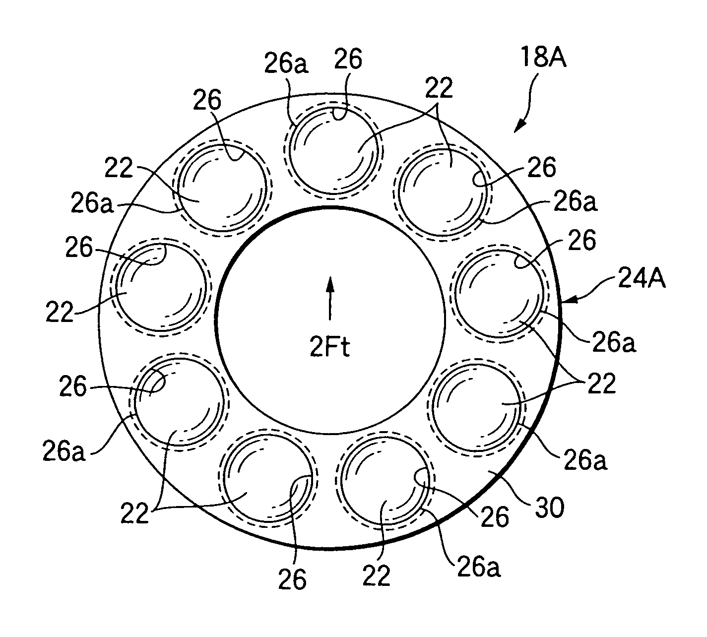
[0038]The power roller bearing 18A comprises an inner ring 20 composed of a portion of the power roller 13, an outer ring 21 disposed to be opposed to the inner ring 20, a plurality of balls 22 respectively stored between a raceway 21a formed in the outer ring 21 and a raceway 20a formed in the inner ring 20, a ring-shaped retainer 24A for holding the balls 22 so as to be able to rotate...

second embodiment

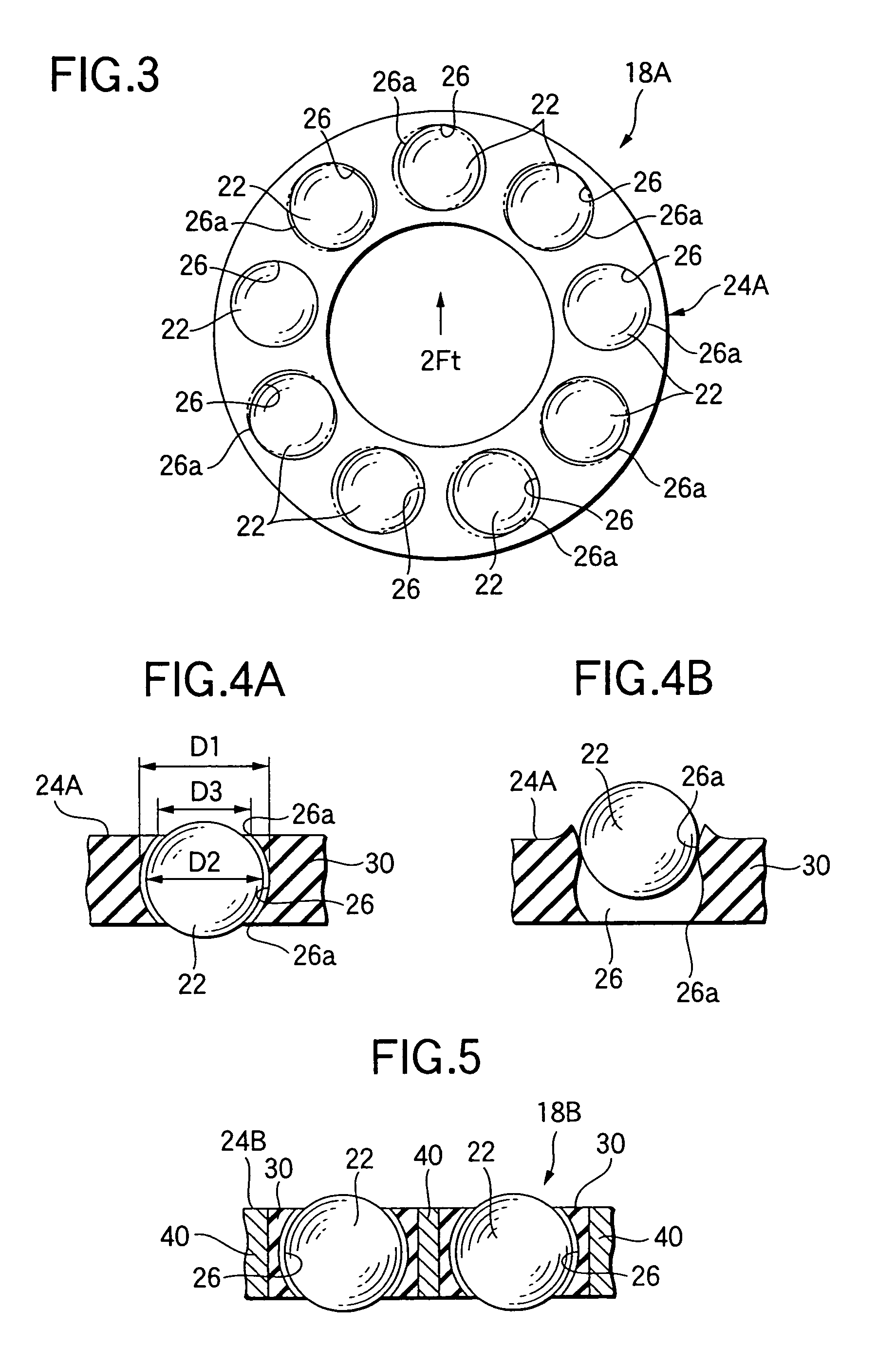
[0045]Now, FIG. 5 shows a portion of a power roller bearing 18B according to the invention. In the case of the present power roller bearing 18B, a retainer 24B includes an elastic material 30 forming the inner peripheral portion of a pocket 26 and a frame member 40 made of high-rigidity material such as metal. In case where a large force is applied to a retainer as in a toroidal-type continuously variable transmission which provides a high output, such a combination of the elastic material 30 and frame member 40 as in the present embodiment can enhance the strength of the retainer 24B.

[0046]By the way, in the above-mentioned power roller bearings 18A, 18B, in case where there is formed an oil groove which communicates with the pocket 26, supply of the lubricating oil (traction oil) to the pocket 26 can be facilitated.

third embodiment

[0047]Now, FIG. 6 shows a portion of a power roller bearing 18C according to the invention. In the present power roller bearing 18C, a plurality of pockets 26C are formed at equi-distant positions in the peripheral direction of a retainer 24C. By the way, in FIG. 6, as the representatives of these pockets 26C, there are shown only the two pockets 26C formed at two positions which are disposed to be opposed by 180° to each other. Each of the pockets 26C is an elongated hole which is slightly longer in the peripheral direction of the retainer 24C. In the interior of each pocket 26C, there are disposed a pair of suspension mechanisms 50 which are opposed to each other with a ball 22 between them.

[0048]Each of the suspension mechanisms 50 includes a member 51 to be contacted with the ball 22 and an elastic member 52 for energizing the member 51 toward the ball 22. As typically shown in FIG. 7, the elastic member 52 has not only the function of a spring 53 but also the function of a damp...


PUM


Abstract

A power roller bearing for rotatably supporting a power roller of a toroidal-type continuously variable transmission, having: an inner ring; an outer ring; a plurality of balls respectively interposed between the inner and outer rings; and, a retainer for holding the balls therein, wherein the retainer includes a plurality of pockets for storing the balls therein at equi-distant positions in the peripheral direction of the retainer, and the inner peripheral portions of the pockets are respectively formed of elastic material that, when the power roller rotates, allows the balls to shift from the equi-distant positions.

Description

[0001]This is a divisional of Application Ser. No. 10 / 262,833 filed Oct. 3, 2002 now U.S. Pat. No. 6,749,343; the disclosure of which is incorporated herein by reference.BACKGROUND OF THE INVENTION[0002]The present invention relates to a power roller bearing for a toroidal-type continuously variable transmission for use, for example, in a power transmission system of a vehicle.[0003]A half-toroidal-type continuously variable transmission, as shown partially in FIGS. 9 and 10, comprises a power roller 13 between an input disk 11 and an output disk 12. The power roller 13 rotates about a displacement shaft 15 which is disposed on a trunnion 14. The trunnion 14 is supported by a pair of trunnion shafts 16 so as to be swung with respect to a support body 17. Between the trunnion 14 and power roller 13, there is interposed a power roller bearing 18.[0004]The power roller bearing 18 comprises an inner ring 20 composed of a portion of the power roller 13, an outer ring 21 disposed to be op...

Claims


Application Information

Patent Timeline
Patent Type & Authority Patents(United States)
IPC IPC(8): F16C19/10F16C19/16F16C33/38F16C33/44F16H15/38
CPCF16C19/10F16H15/38F16C33/3856F16C33/3831
Inventor KATO, HIROSHIMACHIDA, HISASHISHIMIZUYA, MASAYOSHI
Owner NSK LTD
Why Eureka
Try Eureka