Method for forming fine electrode patterns

a fine electrode and pattern technology, applied in the manufacture of electrode systems, electric discharge tubes/lamps, instruments, etc., can solve the problems of significant migration problem, increased sensitivity to metal migration, and substantial investment in plants and equipmen

Inactive Publication Date: 2011-04-21
EI DU PONT DE NEMOURS & CO
View PDF8 Cites 12 Cited by
  • Summary
  • Abstract
  • Description
  • Claims
  • Application Information

AI Technical Summary

Problems solved by technology

As the patterns to be formed become ever finer, they are increasingly susceptible to the problem of metal migration in the conductive pattern.
The problem of migration is significant at areas where electrodes become nar

Method used


Image

  • Method for forming fine electrode patterns
  • Method for forming fine electrode patterns
  • Method for forming fine electrode patterns

Examples


example 1

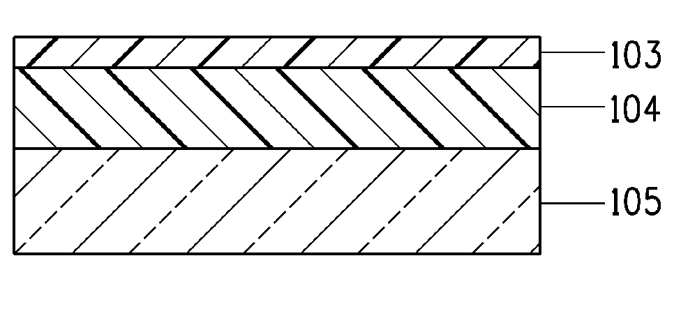
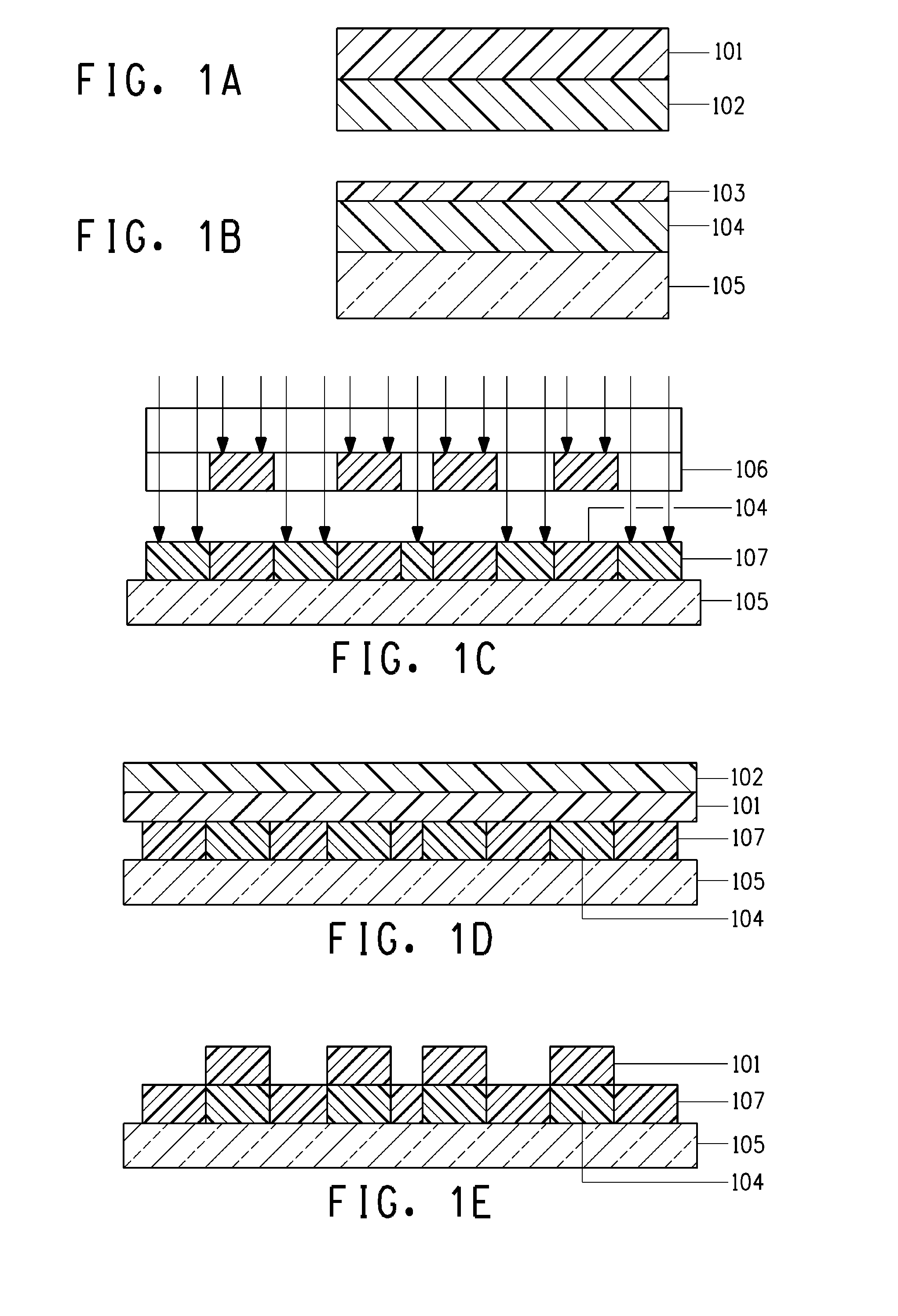
[0048]1. A photosensitive silver paste comprising silver powder, glass frit, an organic binder, monomers, a polymerization initiator and a solvent was printed onto a glass substrate using a screen, and was dried for 5 minutes at 80° C. The paste was exposed to parallel 365 nm UV rays at 400 mJs, using a negative-type photomask for electrodes. The paste was then developed using a 0.4% aqueous solution of Na carbonate, to yield an electrode pattern.

[0049]2. After development, the electrode pattern was pre-fired at 450° C. in order to increase the film strength of the electrodes.

[0050]3. A transfer film having an adhesive surface was affixed using a hot laminator, at 5 kg / cm and 120° C., onto the substrate having the electrodes formed thereon, in such a manner that the transfer film overlapped with the end portion of the electrode pattern. A cover sheet was disposed on the surface of the transfer film. The transfer film was exposed to parallel 365 nm UV rays at 20 mJs, using a positive...

example 2

[0052]Electrodes were formed in the same way as in Example 1, but omitting herein the preliminary firing (process 2).


PUM

PropertyMeasurementUnit
Distanceaaaaaaaaaa
Distanceaaaaaaaaaa
Widthaaaaaaaaaa

Abstract

The present invention is an electrode of an electric device, having a portion at which a pattern is formed using a photosensitive paste, and a portion at which a pattern is formed using a transfer method. Described is a method in which migration at an electrode portion is curtailed by using a photosensitive paste to form a pattern at areas where electrode width is comparatively large, and by forming a pattern using a transfer method at areas where electrode width becomes narrower.

Description

FIELD OF THE INVENTION[0001]The invention relates to a method of forming an electrically functional pattern on a substrate and an electrode formed by using such method.TECHNICAL BACKGROUND OF INVENTION[0002]Photosensitive pastes are one means used in manufacturing fine electrodes in electric devices such as plasma display panels (PDPs) or the like. Photosensitive pastes ordinarily comprise a conductive powder, including materials such as silver, glass frit, an organic binder, monomers, a polymerization initiator, and a solvent. The photosensitive paste is applied on the portion of a substrate where an electrode is to be formed, and then light, corresponding to the polymerization initiator, is irradiated onto desired portions. The monomer component in the irradiated portions undergoes polymerization. These portions are developed thereafter with a developer, as a result of which a desired electrode pattern is formed. The pattern is then fired to yield an electrode in which the conduct...

Claims


Application Information

Patent Timeline
IPC IPC(8): B32B3/10G03F7/20
CPCH01J9/02H01J2211/225H05K3/02Y10T428/24802H05K2201/09727H05K2203/0514H05K2203/0525H05K3/046
Inventor HAYASHI, ISAOMURAKAMI, MAMORUSATO, ATSUHIKO
Owner EI DU PONT DE NEMOURS & CO
Why Eureka
Try Eureka