Intervertebral implant with joint elements carried by universal joint

a universal joint and intervertebral technology, applied in the field of intervertebral implants, can solve the problems of abrasion and resistance, wear on the surface, and generating disadvantageous friction forces, and achieve the effect of facilitating the insertion into the intervertebral spa

Inactive Publication Date: 2011-04-21
DEPUY SYNTHES PROD INC
View PDF13 Cites 43 Cited by
  • Summary
  • Abstract
  • Description
  • Claims
  • Application Information

AI Technical Summary

Benefits of technology

[0019]In a further embodiment of the intervertebral implant according to the invention, a means can be attached to the two sections from the ventral side areas which holds the two sections ventral at a fixed distance relative to each other. This measure provides the advantage that the two sections for insertion into the intervertebral space can be brought to a position with fixed height and can be moved around the joint after insertion into the intervertebral space and can be placed on the base or cover plate of the adjoining vertebral body.
[0020]In a further embodiment of the intervertebral implant according to the invention, the means allows temporary blocking of the mobility of the two sections around the joint. This measure provides the advantage that the joint integrated in the intervertebral space can be blocked by a minimum invasive operation. This is particularly advantageous in cases where the patient suffers from post-operative pain, i.e. where degeneration of the affected spinal column segment continues and the surgeon is considering a fusion of the affected vertebra. The means can preferably be attached to the two ventral side areas of the two sections. With this subsequent, secondary blocking of the mobility of the two sections around the joint, the intervertebral implant is stiffened and transferred to an arthrodesis implant (fusion cage).
[0022]In a further embodiment of the intervertebral implant according to the invention, the means comprises an insert, which can be placed into each depression on the surfaces of the upper and lower section opposite each other. These depressions are preferably provided as dovetail guides that are open on the ventral side areas, so that the ends of the insert arranged complementary to the dovetail guides can be inserted from ventral into the dovetail guides. This provides the advantage that the mobility of the two sections around the joint is blocked due to the positioning of the insert. The rigidity of the blocking can be increased when the dovetail guides are designed so that they are reduced is size towards the central axis of the intervertebral implant, which creates additional wedging of the insert in the dovetail guides.
[0025]In a further embodiment of the intervertebral implant according to the invention, the drill holes for receiving the bone fixation means are provided with internal threads, which allows additional, rigid fixing of the bone fixation means in the two sections. The drill holes preferably have a conical shape so that a stronger fixing of the bone fixation means to each of the two sections can be achieved by the resulting conical thread connections between the internal threads and the external threads on the heads of the bone fixation means.
[0029]C) release and removal of the device inserted into the intervertebral implant for blocking the joint(s). Blocking the joint provides the advantage that the moveable sections with the external apposition surfaces can be inserted more easily into the intervertebral space to be treated.
[0030]In a further application of the process according to the invention, this comprises the subsequent blocking of the joint(s) on the implanted intervertebral implant by means of the device intended for blocking the joint(s). This provides the advantage that if the patient should suffer from post-operative pains or in case of a further degeneration of the movement segment, the joint(s) on the intervertebral implant are blocked postoperative by the insertion of the means intended for this purpose. This subsequent blocking can be achieved with an minimally invasive, preferably a laparoscopic operation. The intervertebral implant then assumes the function of a cage, so that the affected movement segment of the spinal column can be stiffened.

Problems solved by technology

The disadvantages of this known intervertebral disk endoprosthesis is that
c) disadvantageous friction forces are generated by two articulating surfaces sliding on each other.
This also leads to wear on the surfaces, including also abrasion and resistance in movement of the joint elements.
There is also the risk of the “stick slip” effect;
d) a mechanical intervertebral disk prosthesis can scarcely prevent the further degeneration of the affected movement segments.
This operation represents extreme discomfort and strain on the patient; and

Method used


Image

  • Intervertebral implant with joint elements carried by universal joint
  • Intervertebral implant with joint elements carried by universal joint
  • Intervertebral implant with joint elements carried by universal joint

Examples


Embodiment Construction

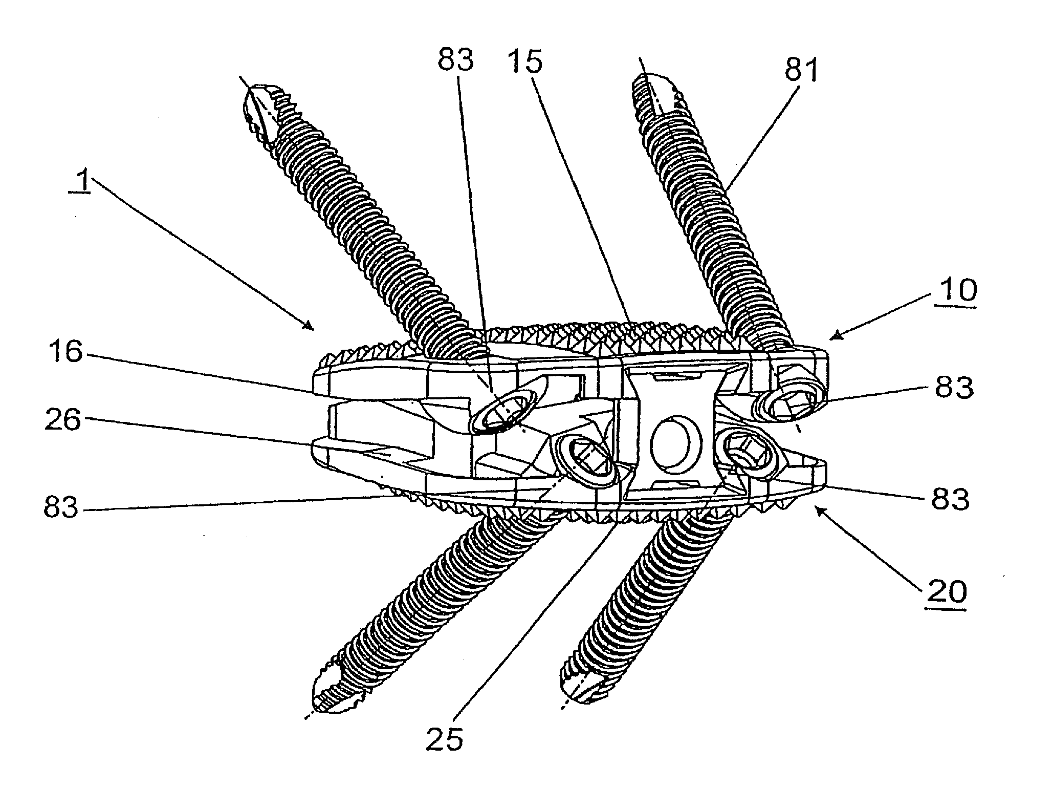
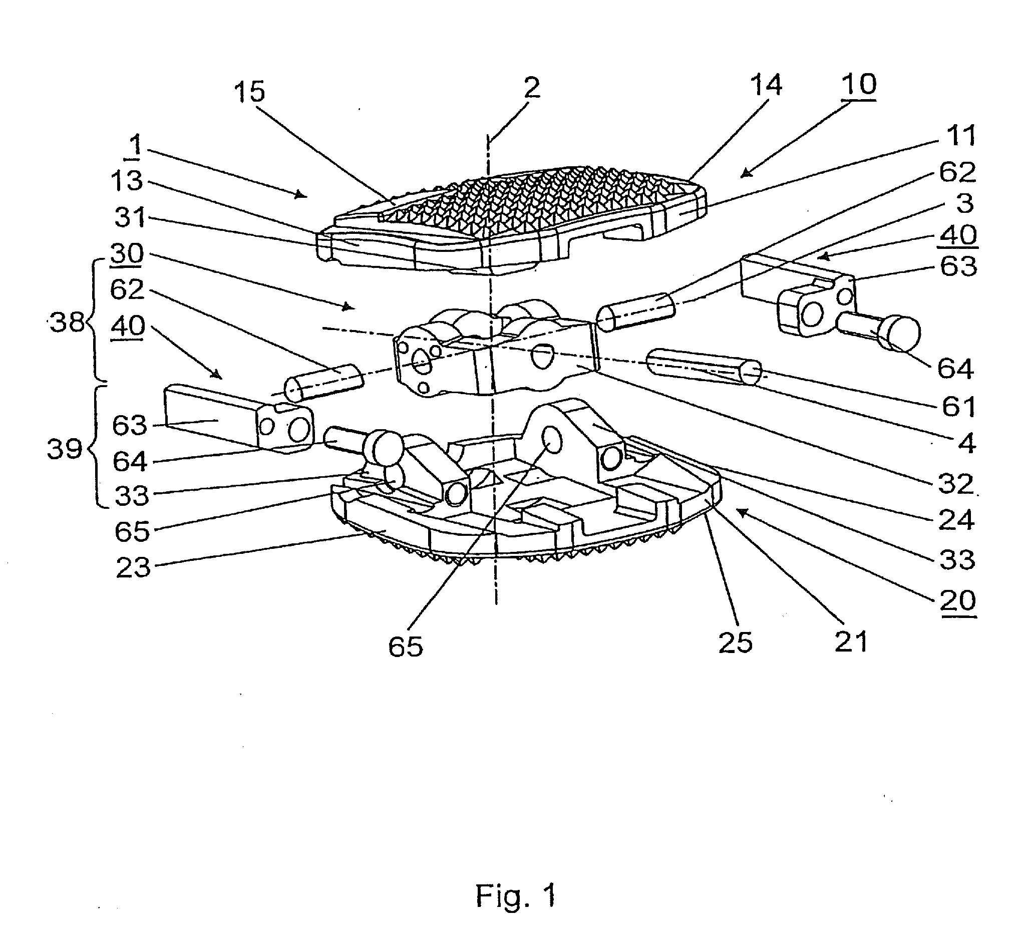
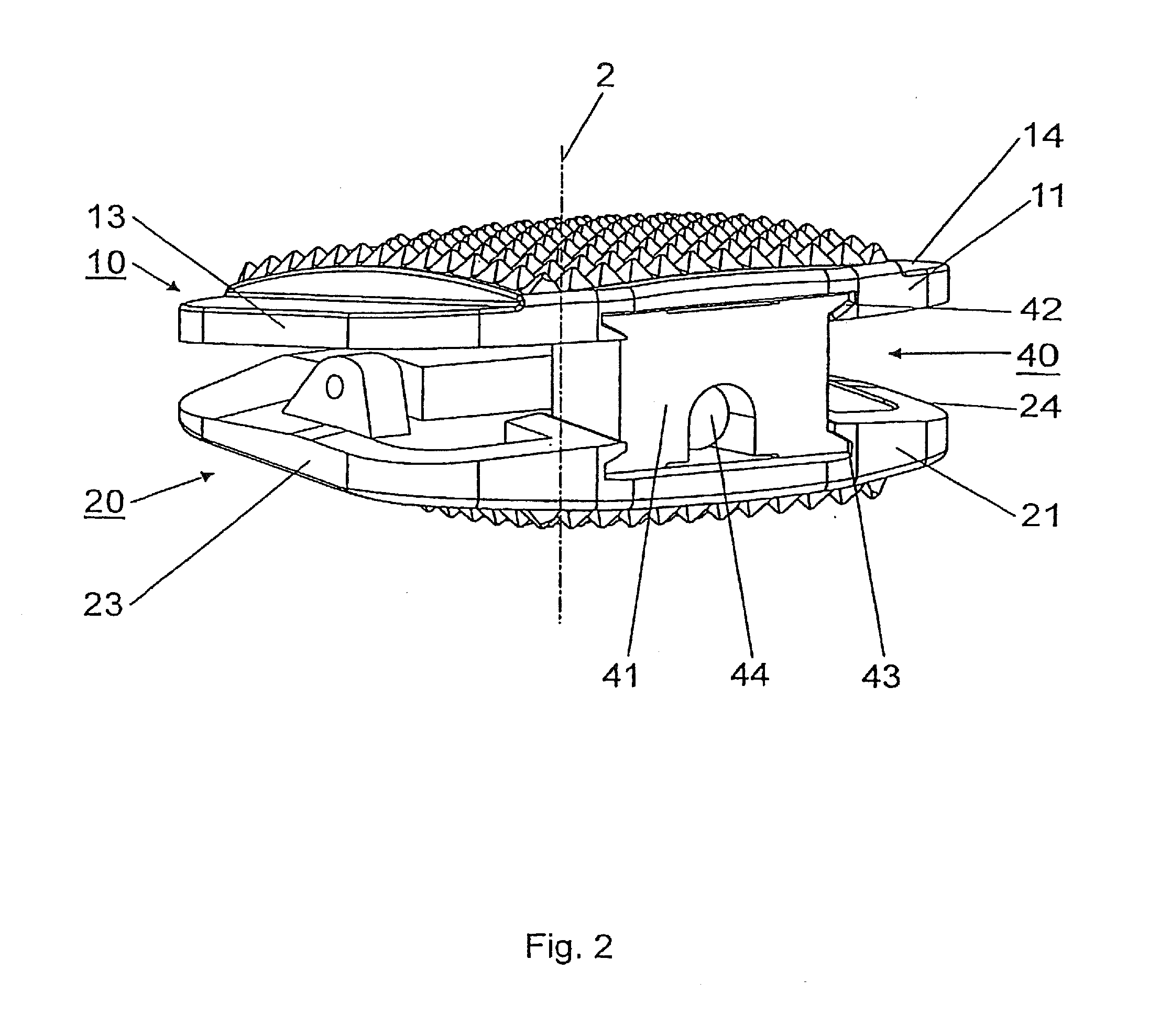
[0036]An embodiment of the intervertebral implant according to the invention 1 is illustrated in FIG. 1 and comprises an upper section 10 with an upper apposition surface 15 arranged perpendicular to the central axle 2 for laying onto the base plate of a neighbouring vertebral body, a lower section 20 with a lower apposition surface 25 arranged perpendicular to the central axle 2 for laying onto the cover plate of the neighbouring vertebral body and a joint 30. The upper section 10 and the lower section 20 are linked in a way that allows movement in relation to each other by means of the joint 30, wherein the mobility of the upper section 10 relative to the lower section 20 around a first swivel axle 3 arranged perpendicular to the central axle 2 is limited within an angle range of between +10° and −60 and around a second swivel axle 4 arranged perpendicular to the central axle 2 and vertical to the first swivel axle 3 is limited within an angle range of ±7°.

[0037]The joint 30 is ar...


PUM


Abstract

An intervertebral implant, specifically an artificial intervertebral disk, with a central axis, an upper section, suitable for laying onto the base plate of a vertebral body lying on top and lower section, suitable for laying onto the cover plate of a vertebral body lying below, wherein(A) the upper section is provided with a ventral side area, a dorsal side area, two lateral side areas, a top apposition surface and a bottom surface;(B) the lower section is provided with a ventral side area, a dorsal side area, two lateral side areas, a bottom apposition surface and a top surface;(C) the two sections are moveable in relation to each other by means of one joint arranged between the two sections, wherein(D) the joint is a universal joint with two swivel axles standing perpendicular to each other.

Description

CROSS REFERENCE TO RELATED APPLICATION[0001]This application is a continuation of U.S. patent application Ser. No. 10 / 538,542, filed Jun. 8, 2007, entitled “INTERVERTEBRAL IMPLANT WITH JOINT ELEMENTS CARRIED BY UNIVERSAL JOINT” which claims the benefit of International Application No. PCT / CH2002 / 000706, filed Dec. 17, 2002, the entire contents of these applications is incorporated herein by reference.BACKGROUND OF THE INVENTION[0002]The invention relates to an intervertebral implant and to a process for the replacement of a defect, natural intervertebral disk by an intervertebral implant.[0003]After removal of a damaged, natural intervertebral disk or a damaged nucleus pulposus of an intervertebral disk, implants or prostheses are inserted into the intervertebral space of two neighbouring vertebral bodies. This suggests the idea of restoring the situation as much as possible to a natural state, Le. specifically to restore the original height of the intervertebral disk and thus the o...

Claims


Application Information

Patent Timeline
Patent Type & Authority Applications(United States)
IPC IPC(8): A61F2/44A61B17/86A61F2/00A61F2/30A61F2/46
CPCA61B17/86A61F2220/0033A61F2/4425A61F2/4455A61F2002/30362A61F2002/30387A61F2002/30492A61F2002/30507A61F2002/30515A61F2002/30517A61F2002/30528A61F2002/30604A61F2002/30632A61F2002/30634A61F2002/30635A61F2002/30774A61F2002/30785A61F2002/30787A61F2002/30794A61F2002/30843A61F2002/443A61F2002/4635A61F2220/0025A61B17/863A61F2002/3079
Inventor AEBI, MAXBURKARD, DOMINIQUEFRIGG, ROBERTLECHMANN, BEATMATHYS, JR., ROBERTPAVLOV, PAUL
Owner DEPUY SYNTHES PROD INC
Why Eureka
Try Eureka