

Driving tool
a technology of driving motor and driving shaft, which is applied in the direction of nailing tools, stapling tools, and clutches, etc., can solve the problems of possible faulty driving operation, and achieve the effect of preventing faulty driving of the material to be driven, reducing the maximum starting current at the time of starting the driving motor, and preventing the decrease of battery li
- Summary
- Abstract
- Description
- Claims
- Application Information
AI Technical Summary
Benefits of technology
Problems solved by technology
Method used
Image

Examples
Embodiment Construction
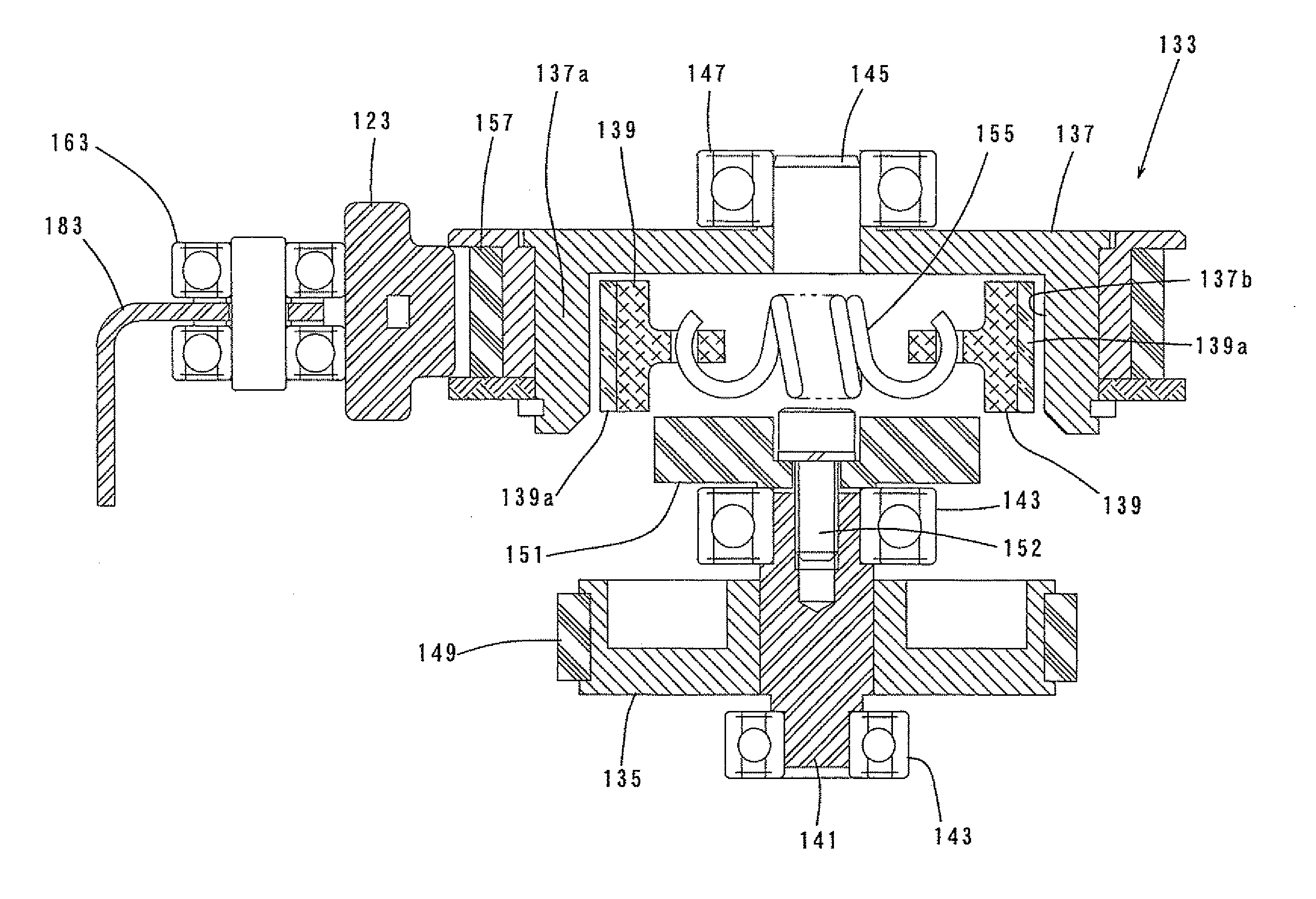
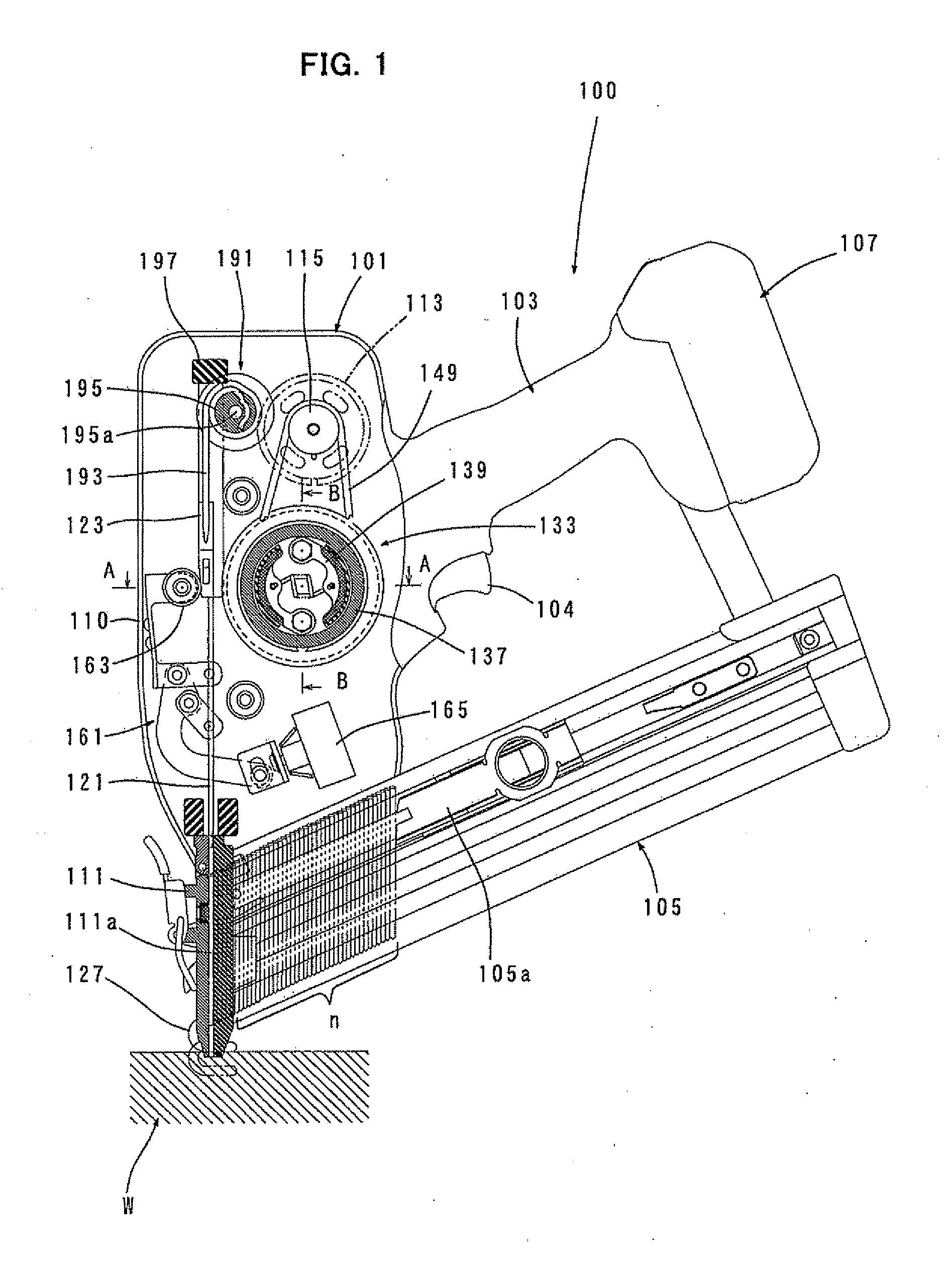
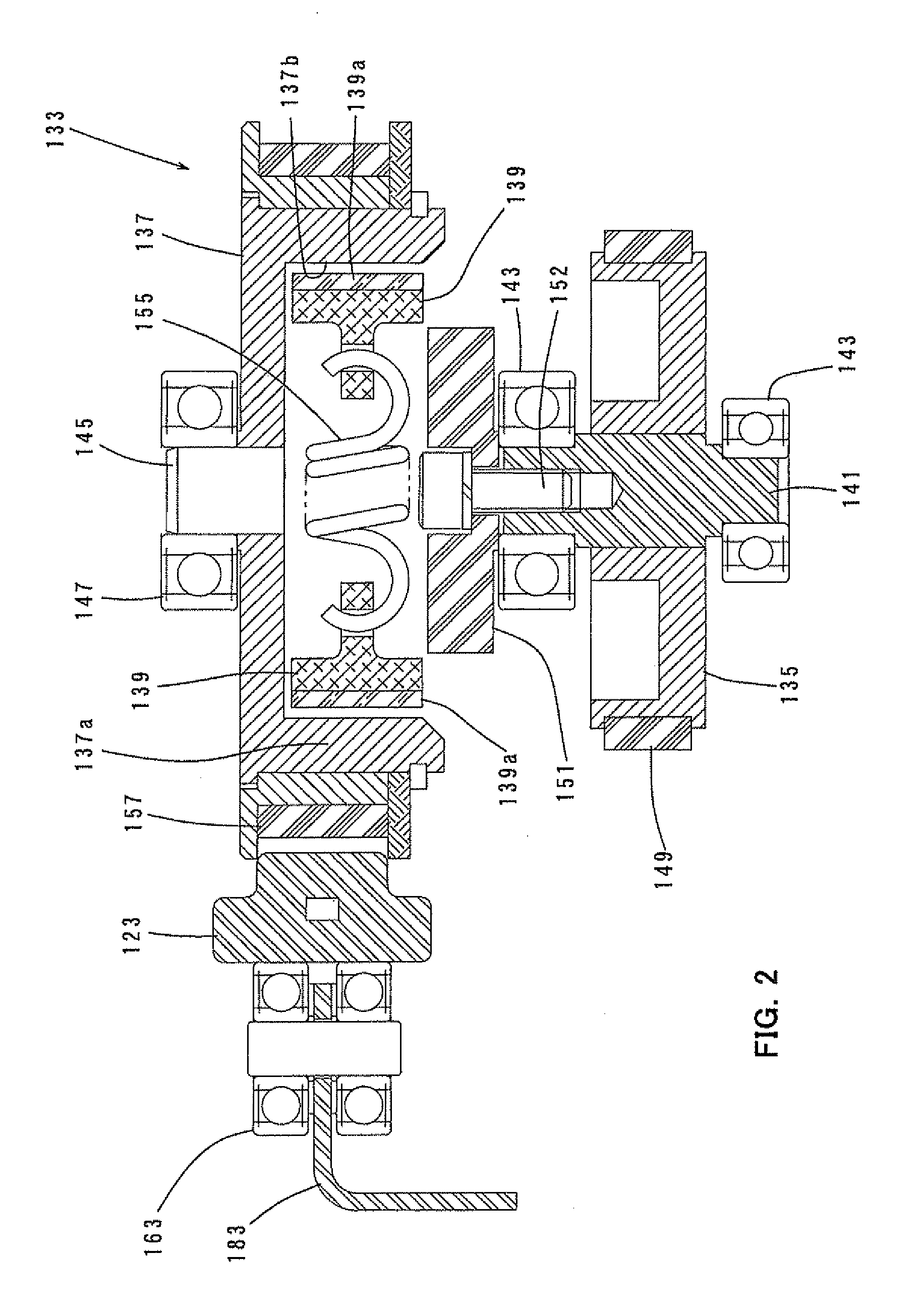
[0016]An embodiment of the invention is now described with reference to the drawings. FIG. 1 shows an entire battery-powered nailing machine 100 as a representative example of a driving tool according to the embodiment of the invention. FIGS. 2 and 3 are sectional views taken along line A-A in FIG. 1, showing a driver driving section. FIG. 4 is a sectional view taken along line B-B in FIG. 1, showing the driver driving section. Further, FIG. 5 shows a centrifugal clutch mounted to a flywheel, and FIG. 6 shows a pressing mechanism that presses a driver against the flywheel.
[0017]As shown in FIG. 1, the nailing machine 100 includes a body 101 that forms an outer shell of the nailing machine 100, a handle 103 to be held by a user, and a magazine 105 that is loaded with nails n to be driven into a workpiece. The handle 103 is integrally formed with the body 101 and extends from the side of the body 101 in a lateral direction transverse to the longitudinal direction of the body 101 (the ...
PUM
| Property | Measurement | Unit |
|---|---|---|
| rotating force | aaaaa | aaaaa |
| rotation speed | aaaaa | aaaaa |
| speed | aaaaa | aaaaa |
Abstract
Description
Claims
Application Information