
Electronic document reading devices

a document reading and electronic technology, applied in the field of thin-film architectures, can solve the problems of large touch screen, thin, special problems of flex-tolerant devices, etc., and achieve the effects of flexing the device, facilitating assembly, and providing flex-toleran

Inactive Publication Date: 2011-04-28
FLEHKSENEHBL LTD
View PDF23 Cites 101 Cited by
  • Summary
  • Abstract
  • Description
  • Claims
  • Application Information

AI Technical Summary

Benefits of technology

[0008]In embodiments the touch sensing layer is electrically connected to the control circuit board at a maximum of two opposite edges of the control circuit board; the display screen may be electrically connected to the control circuit board at two opposite sides or three sides of the control circuit board, to provide row and column (gate select and data) connections to the display. In embodiments of the device the connections to the touch screen are made at the first pair of opposite sides of the control circuit board and connections to the display screen are made at a second, different pair of opposite sides of the control circuit board orthogonal to the first pair (and also on a third side). To achieve the desired longitudinal alignment when assembled, a connection to one of the touch sensing layer and display screen includes a 90° turn, achieved within the very thin housing by a fold in the laminar connector, and thus the longitudinal directions of the laminar connectors at the control circuit board are all aligned along a common longitudinal direction. In this way flexing of the device can be tolerated without substantial stress on the connections to the control circuit board.
[0026]There are special problems in achieving a thin, flex-tolerant electronic document reading device. Embodiments of the above described technique facilitate achieving an appearance of extreme thinness, especially in the context of the previously described architecture, which also facilitates the production of a thin, flexible device. Thus in embodiments the device has a lateral diagonal dimension of at least 25 cm and a physical thickness at the lateral sides of less than 7 mm, in embodiments less than 5 mm. A raised portion or “doghouse” on one side may be employed to provide a connector portion for the device. In embodiments the device has a maximum physical thickness of no greater than 9 mm; embodiments the transparent front panel has a thickness of no greater than 0.3 mm. The edges of the removeable rear panel may be lower than (lie beneath) the rear edges of the front portion of the housing to further sustain the illusion; optionally a gap is provided between a lateral edge of the rear panel and a lateral side wall of the front, transparent portion of the housing. In embodiments the opaque interior surface may be provided by a black pigment, deposited on the interior surface.

Problems solved by technology

However the construction of a large-area, thin, flex-tolerant device with a large touch screen presents special problems.

Method used


Image

  • Electronic document reading devices
  • Electronic document reading devices
  • Electronic document reading devices

Examples


Embodiment Construction

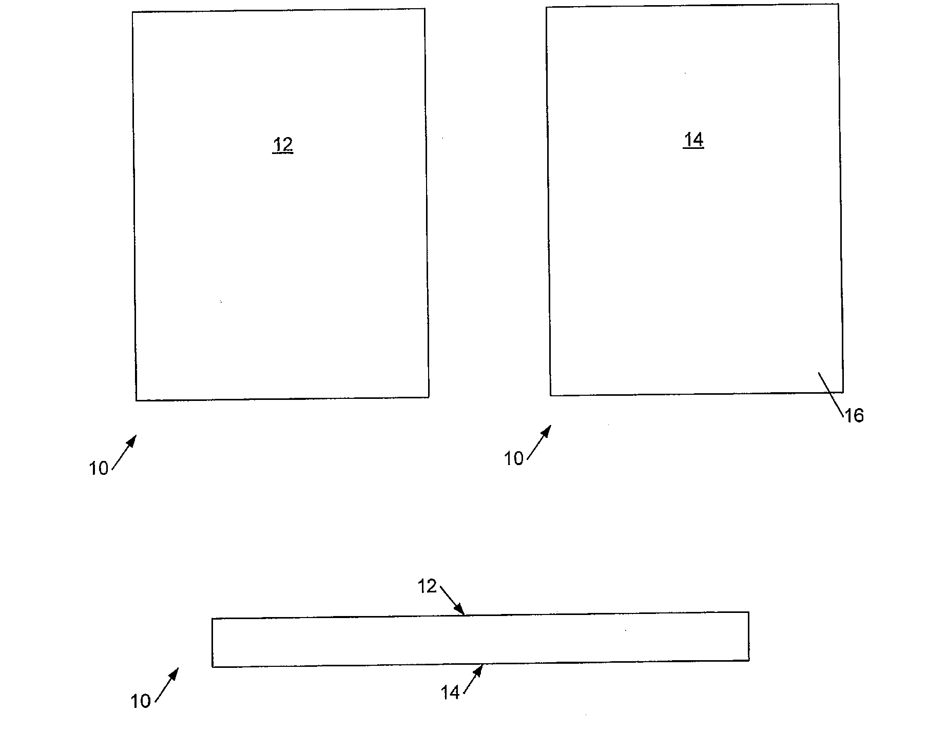
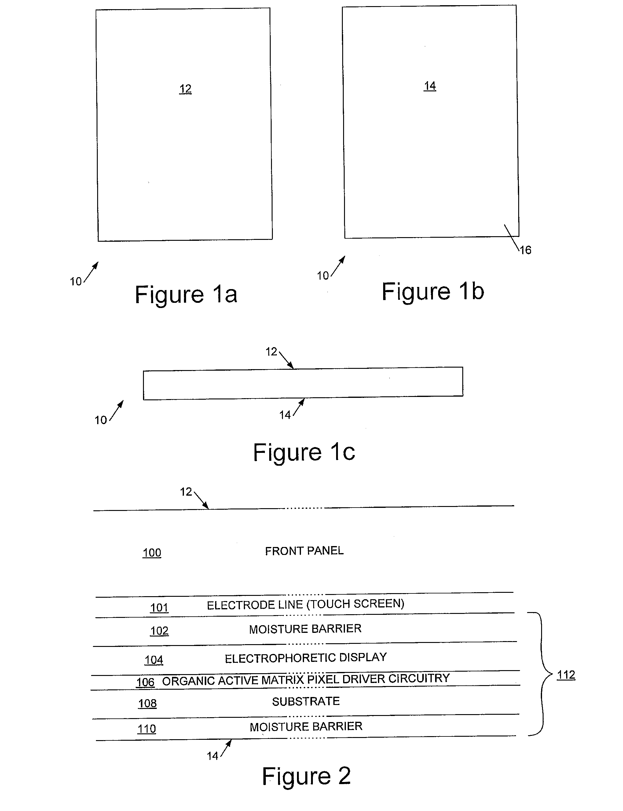
[0041]Referring to FIGS. 1a to 1c, these schematically illustrate an electronic document reading device 10 having a front display face 12 and a rear face 14. As can be seen from FIG. 1c, in preferred embodiments the display surface 12 is substantially flat to the edges of the device, and in particular may lack a display bezel. In some implementations the electronic (electrophoretic) display does not extend right to the edges of the display surface 12, and rigid control electronics are incorporated around the edges of the electronic display—this approach can reduce the overall thickness of the device and thus facilitating flex-tolerance, at the expense of making the overall area of the device slightly larger.

[0042]Referring now to FIG. 2, this illustrates a vertical cross-section through a display region of the device between the frame members 16. The drawing is not to scale.

[0043]As can be seen, in preferred embodiments the device has a substantially transparent front panel 100, for...


PUM


Abstract

We describe an architecture for a large-area, touch-sensitive electronic document reading device which is able to tolerate bending. In broad terms, a control circuit board is mounted behind a flexible display structure in the housing and at respective points of attachment of first and second laminar connectors to the control circuit board each laminar connector has a plurality of electrical connections running along a longitudinal direction of the laminar connector and disposed alongside one another in a transverse direction across the laminar connector. At the respective points of attachment of the first and second laminar connectors to the control circuit board the longitudinal directions of the laminar connectors are aligned such that, when said device is flexed, a relative displacement in said longitudinal direction between said control circuit board and of said display structure can be tolerated without damage to the control electronics, touch sensitive display screen or connections therebetween.

Description

CROSS-REFERENCE TO RELATED APPLICATIONS[0001]This application claims the right of priority to United Kingdom Application No. 0918619.8 entitled “ELECTRONIC DOCUMENT READING DEVICES,” filed on Oct. 23, 2009, which application is incorporated herein by reference.FIELD OF THE INVENTION[0002]This invention relates to architectures for thin, flex-tolerant electronic document reading devices, especially large-area devices.BACKGROUND TO THE INVENTION[0003]Background prior art relating to electronic document reading devices can be found in U.S. Pat. No. 6,124,851, US2004 / 0201633, US2006 / 0133664, US2006 / 0125802, US2006 / 0139308, US2006 / 0077190, US2005 / 0260551, U.S. Pat. No. 6,124,851, U.S. Pat. No. 6,021,306, US2005 / 0151742, and US2006 / 0119615. Examples of electronic document reading devices are the Iliad Hex®, the Amazon Kindle® and the Sony® Reader. Background prior art relating to power saving can be found in: US2007 / 0028086, US2007 / 0115258, and U.S. Pat. No. 7,058,829.[0004]We have previo...

Claims


Application Information

Patent Timeline
Patent Type & Authority Applications(United States)
IPC IPC(8): G06F3/041G09G5/00
CPCG06F1/1626G06F1/1643G09G5/003G06F3/0412G06F3/044G06F1/1652G09G3/344G06F3/0443G06F3/0446G06F15/0216G06F15/0283G06F15/0291
Inventor HAYTON, CARL
Owner FLEHKSENEHBL LTD
Learn More