Optical touch-sensing display

a touch-sensing display and optical technology, applied in the field of touch-sensing displays, can solve the problems of increasing costs and achieve the effect of good quality

Inactive Publication Date: 2011-04-28
SONIX TECH
View PDF10 Cites 14 Cited by
  • Summary
  • Abstract
  • Description
  • Claims
  • Application Information

AI Technical Summary

Benefits of technology

[0010]The invention is directed to an optical touch-sensing display, in which touch units and a transmission interface are integrated to achieve a better touch performance.
[0017]According to the above descriptions, in the optical touch-sensing display of the invention, the light guides are disposed at peripheral of the display surface, so that the light emitted by the light sources may have an good light-emitting quality when being transmitted to the sensing space through the light guides, so that an optical environment of the sensing space and a touch performance of the optical touch-sensing display are improved.
[0018]Moreover, in the optical touch-sensing display of the invention, by using the sensing modules electrically connected to each other and the USB connected thereto, the first signals generated by the sensing modules are transmitted to one of the sensing modules and are processed to the second signal, and then the second signal is output from the sensing module through the USB. In this way, a data transmission amount is reduced due to a pre-computation, so that a data transmission time is shortened, and the optical touch-sensing device become more efficient.
[0019]Moreover, the optical touch module in the optical touch-sensing display is divided into a plurality of optical touch-sensing devices, and the one-dimensional coordinate signals generated by the optical touch-sensing devices are transmitted to one of the optical touch-sensing device having the storage device and are processed to a two-dimensional coordinate signal, and then the two-dimensional coordinate signal is output from the optical touch module through the transmission interface. In this way, the related system chipsets in the optical touch-sensing devices are integrated, so as to improve operating efficiencies of the optical touch module and the optical touch-sensing display.

Problems solved by technology

This way will cause the increasing of cost because of setting a supplemented device including the controller on the screen or a supplemented operating platform connected to the screen.

Method used


Image

  • Optical touch-sensing display
  • Optical touch-sensing display
  • Optical touch-sensing display

Examples


Embodiment Construction

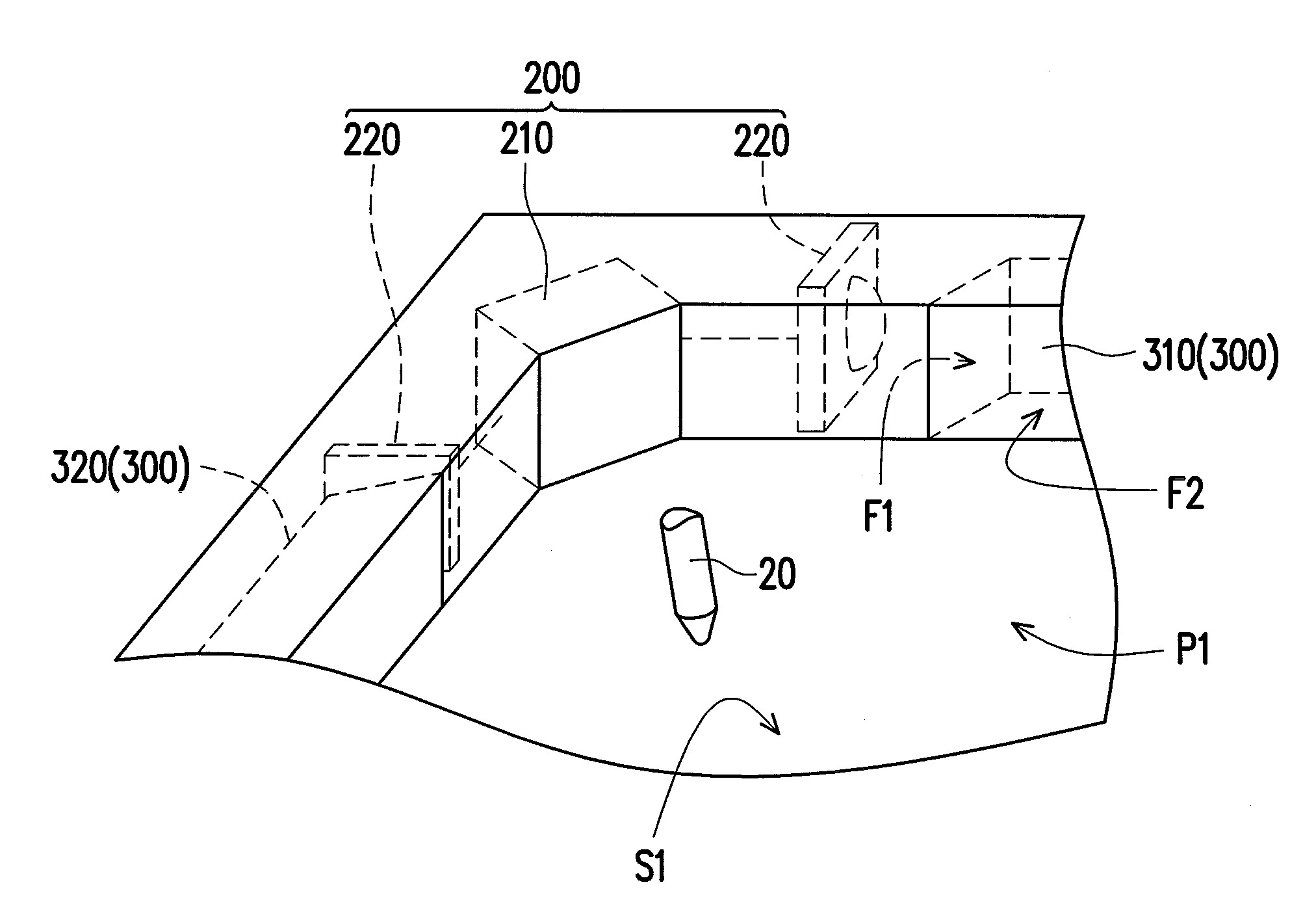
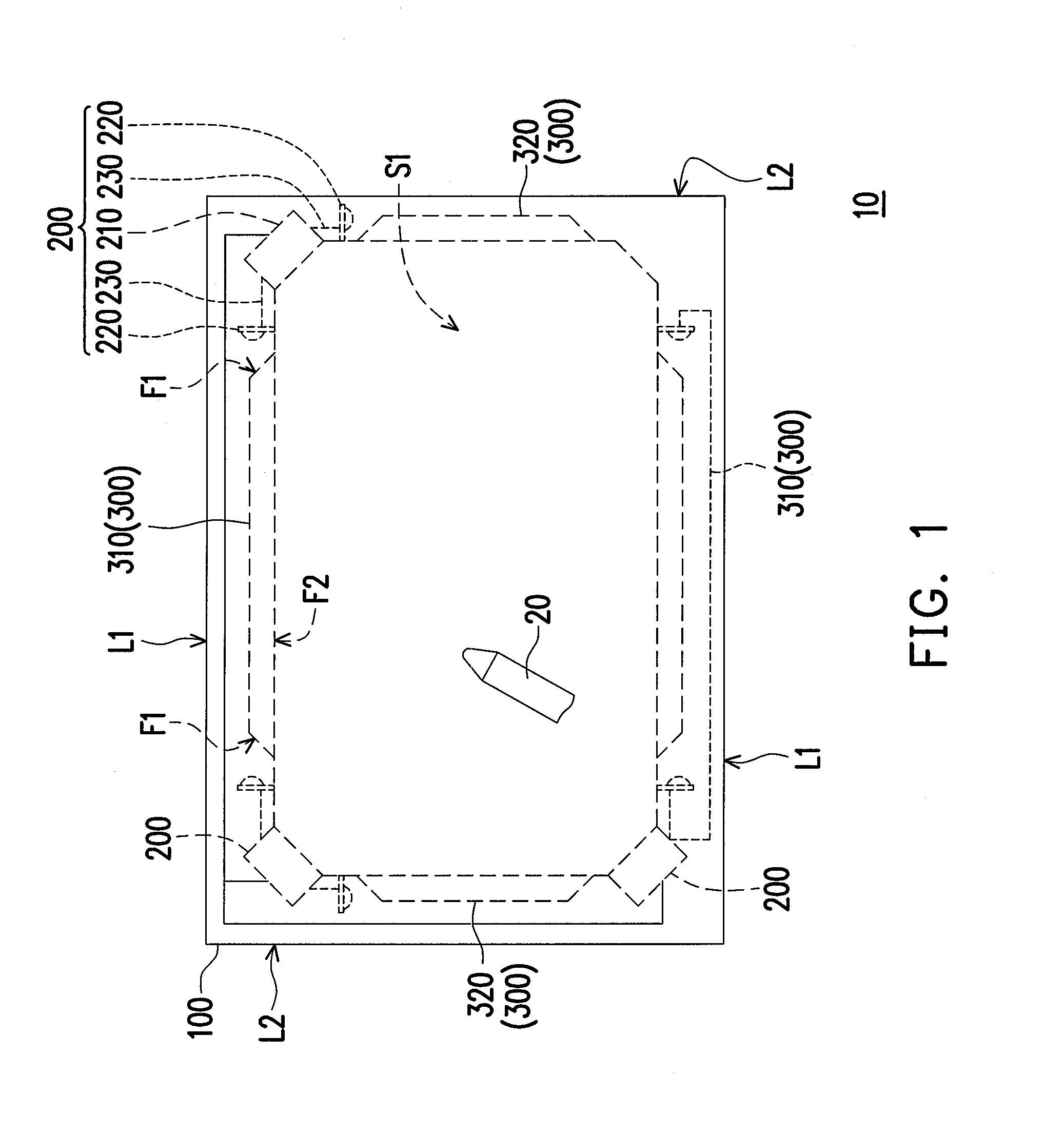
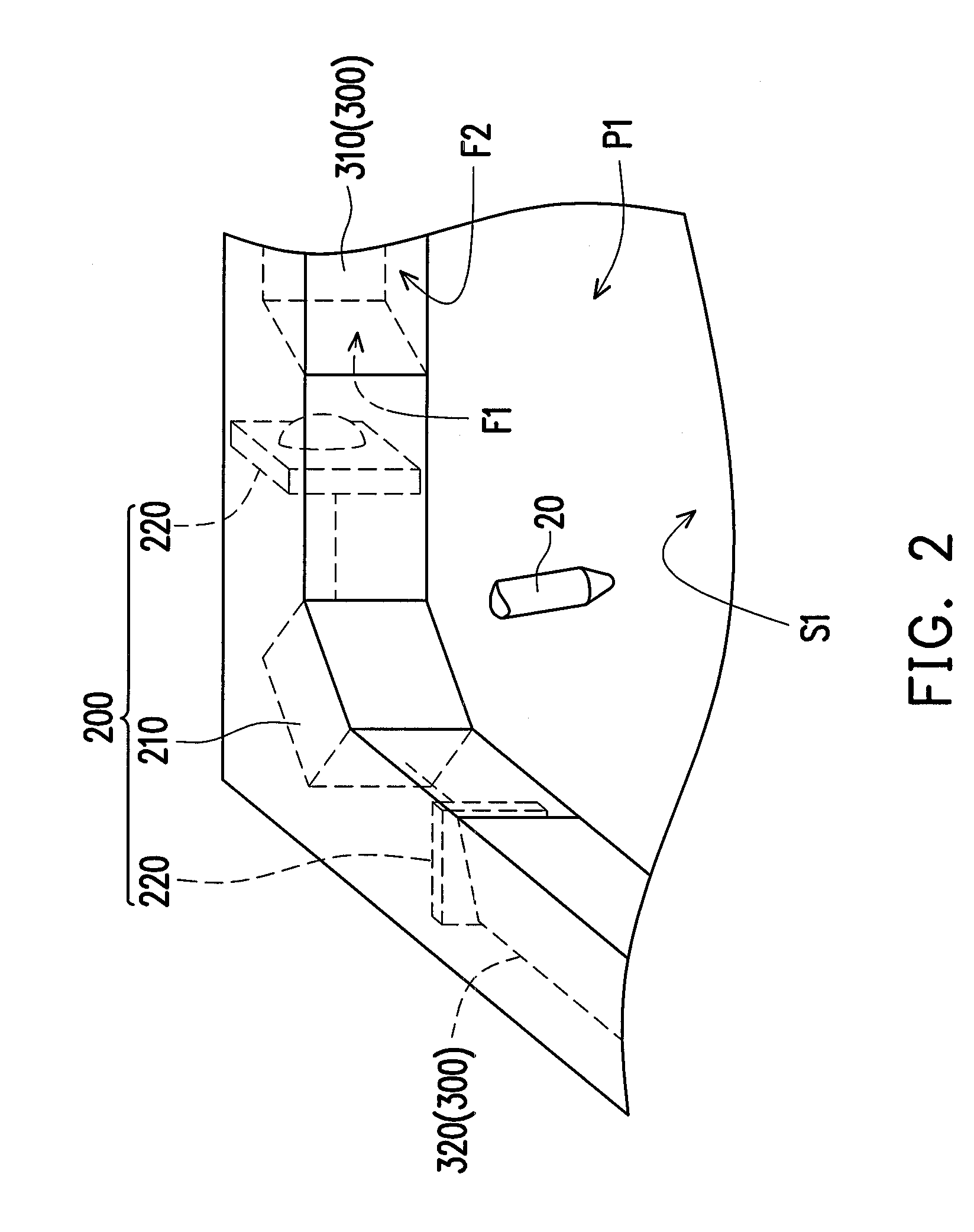
[0029]FIG. 1 is a schematic diagram illustrating an optical touch-sensing display according to an embodiment of the invention. FIG. 2 is a partial three-dimensional view of the optical touch-sensing display of FIG. 1. FIG. 3 is a component block diagram of the optical touch-sensing display of FIG. 1. Referring to FIG. 1 to FIG. 3, in the present embodiment, the optical touch-sensing display 10 includes a display device 100, three optical touch-sensing devices 200, fourth light guides 300 and a transmission interface 400. In the present embodiment, the display device 100 is a liquid crystal display (LCD), and the transmission interface 400 is a universal serial bus (USB), though the invention is not limited thereto, and in another embodiment that is not illustrated, the display device can be any electronic device having a display function, and the transmission interface can also be any related human interface device (HID).

[0030]In FIG. 1 and FIG. 2, to clearly illustrate configuratio...


PUM


Abstract

An optical touch-sensing display including a display device, at least three light guides, at least two optical touch-sensing devices and a transmission interface is provided. The display device has a display surface and a sensing space upon the display surface. Each of the light guides disposed at periphery of the display surface has two light incident surfaces and a light-emitting surface there between. Each of the optical touch-sensing devices disposed outside of the display surface includes a sensing module and a light source. When an object enters the sensing space, each sensing module senses a light variation induced by the object to generate a first signal, and then the first signals are transmitted to one sensing module and processed to a second signal, and then the second signal is output from the optical touch-sensing device through the transmission interface.

Description

CROSS-REFERENCE TO RELATED APPLICATION[0001]This application claims the priority benefits of Taiwan application serial no. 98135962, filed on Oct. 23, 2009, Taiwan application serial no. 98146653, filed on Dec. 31, 2009, Taiwan application serial no. 99102093, filed on Jan. 26, 2010 and Taiwan application serial no. 99116100, filed on May 20, 2010. The entirety of each of the above-mentioned patent application is hereby incorporated by reference herein and made a part of this specification.BACKGROUND[0002]1. Field of the Invention[0003]The invention relates to a touch-sensing display. Particularly, the invention relates to an optical touch-sensing display.[0004]2. Description of Related Art[0005]In recent years, with continuous progress of image display technique, since a touch screen has an advantage of conducting input directly through a touch operation, it has become a commonly used display device in the market, and is widely applied in various electronic produces such as an auto...

Claims


Application Information

Patent Timeline
Patent Type & Authority Applications(United States)
IPC IPC(8): G06F3/042
CPCG06F3/0428
Inventor HUANG, YEN-LANG
Owner SONIX TECH
Why Eureka
Try Eureka