
Power electronics assembly with multi-sided inductor cooling

Active Publication Date: 2011-04-28
GM GLOBAL TECH OPERATIONS LLC
View PDF9 Cites 35 Cited by
  • Summary
  • Abstract
  • Description
  • Claims
  • Application Information

AI Technical Summary

Problems solved by technology

One of the changes involves the complexity of the electrical systems within automobiles, particularly alternative fuel (or propulsion) vehicles that utilize voltage supplies, such as hybrid and battery electric vehicles.

Method used


Image

  • Power electronics assembly with multi-sided inductor cooling
  • Power electronics assembly with multi-sided inductor cooling
  • Power electronics assembly with multi-sided inductor cooling

Examples


Embodiment Construction

[0021]The following detailed description is merely exemplary in nature and is not intended to limit the invention or the application and uses of the invention. Furthermore, there is no intention to be bound by any expressed or implied theory presented in the preceding technical field, background, and brief summary, or the following detailed description.

[0022]The following description refers to elements or features being “connected” or “coupled” together. As used herein, “connected” may refer to one element / feature being mechanically joined to (or directly communicating with) another element / feature, and not necessarily directly. Likewise, “coupled” may refer to one element / feature being directly or indirectly joined to (or directly or indirectly communicating with) another element / feature, and not necessarily mechanically. However, it should be understood that although two elements may be described below, in one embodiment, as being “connected,” in alternative embodiments similar el...


PUM


Abstract

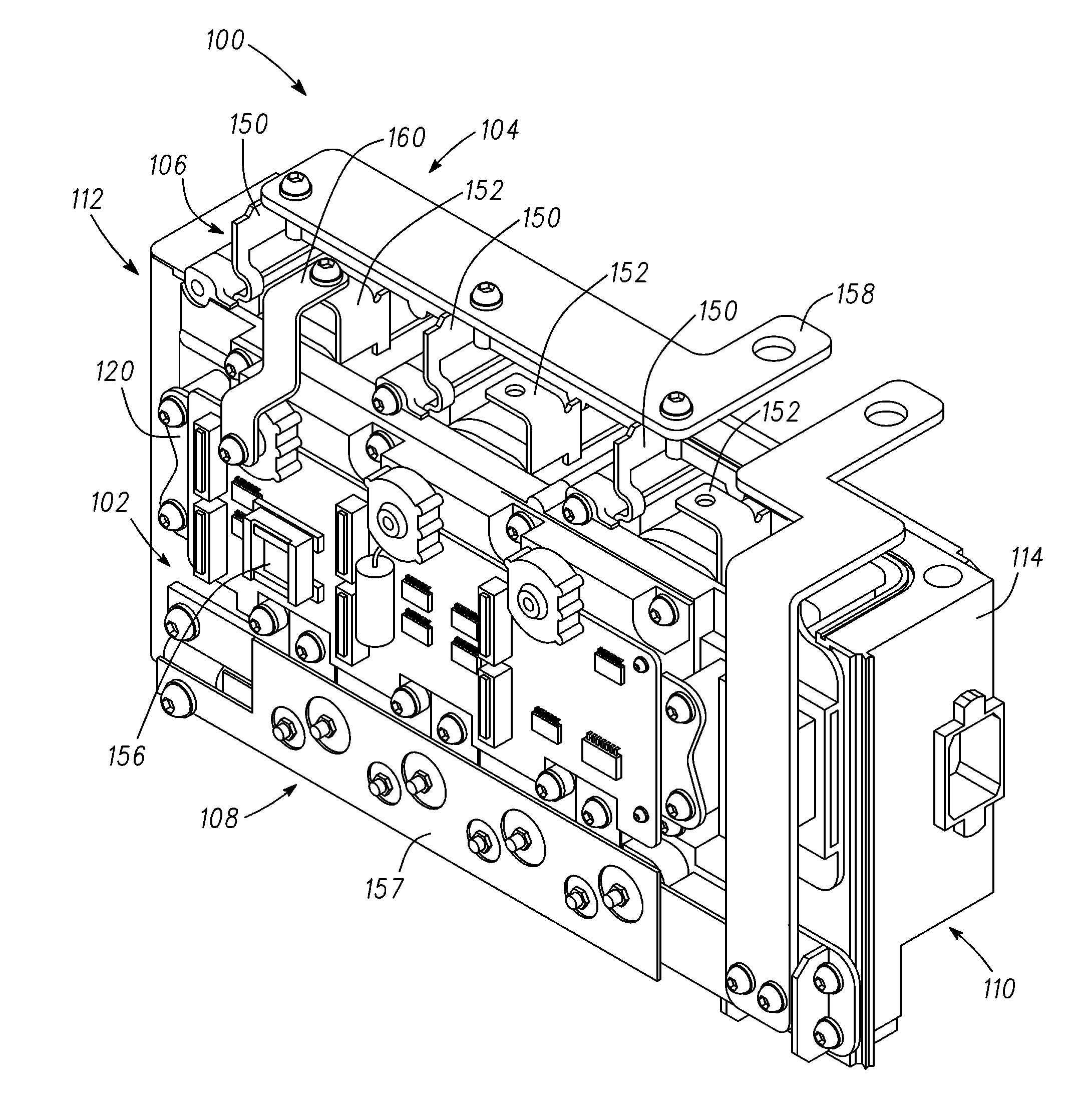
A power electronics assembly is provided. The assembly includes a housing defining at least one cavity and having a fluid passageway extending therethrough, the fluid passageway having first and second portions on respective first and second opposing sides of the at least one cavity, and a plurality of inductors housed within the at least one cavity of the housing such that the first and second portions of the fluid passageway are on first and second opposing sides of each of the plurality of inductors.

Description

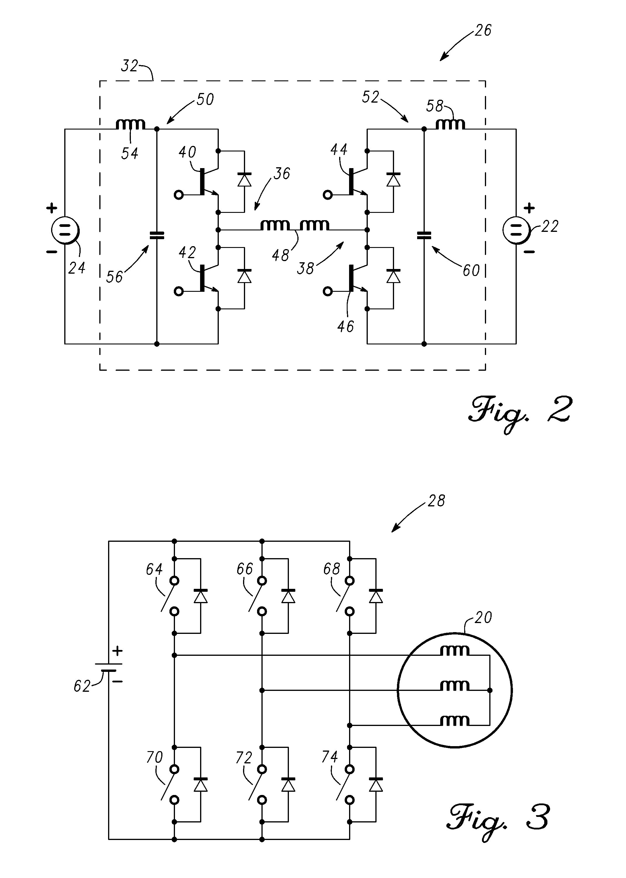
TECHNICAL FIELD[0001]The present invention generally relates to power electronics, and more particularly relates to an automotive power electronics assembly with multi-sided inductor cooling.BACKGROUND OF THE INVENTION[0002]In recent years, advances in technology, as well as ever-evolving tastes in style, have led to substantial changes in the design of automobiles. One of the changes involves the complexity of the electrical systems within automobiles, particularly alternative fuel (or propulsion) vehicles that utilize voltage supplies, such as hybrid and battery electric vehicles. Such alternative fuel vehicles typically use one or more electric motors, often powered by batteries, perhaps in combination with another actuator, to drive the wheels.[0003]Such vehicles often use two separate voltage sources, such as a battery and a fuel cell, to power the electric motors that drive the wheels. Power electronics (or power electronics systems), such as direct current-to-direct current (...

Claims


Application Information

Patent Timeline
IPC IPC(8): H05K7/20H01F27/08
CPCH01F27/025H05K7/20927H02M7/003
Inventor DOO, YOUNG M.KORICH, MARK D.TRIANTOS, KONSTANTINOS
Owner GM GLOBAL TECH OPERATIONS LLC
Features
  • Generate Ideas
  • Intellectual Property
  • Life Sciences
  • Materials
  • Tech Scout
  • Unparalleled Data Quality
  • Higher Quality Content
  • 60% Fewer Hallucinations
Learn More