Method for estimating target range error and sonar system thereof

Active Publication Date: 2011-04-28
AGENCY FOR DEFENSE DEV +1
View PDF1 Cites 12 Cited by
  • Summary
  • Abstract
  • Description
  • Claims
  • Application Information

AI Technical Summary

Benefits of technology

[0015]Therefore, an object of the present invention is to provide a method capable of precisely calculating a detection target range by predicting a path of a sound pulse (ray) fro

Problems solved by technology

However, a long time and a complicated acoustic sensor are required to detect a target range.
However, if one uses just one value of sound velocity such as the reference value in water depth, one may not obtain exact tar

Method used


Image

  • Method for estimating target range error and sonar system thereof
  • Method for estimating target range error and sonar system thereof
  • Method for estimating target range error and sonar system thereof

Examples


first embodiment

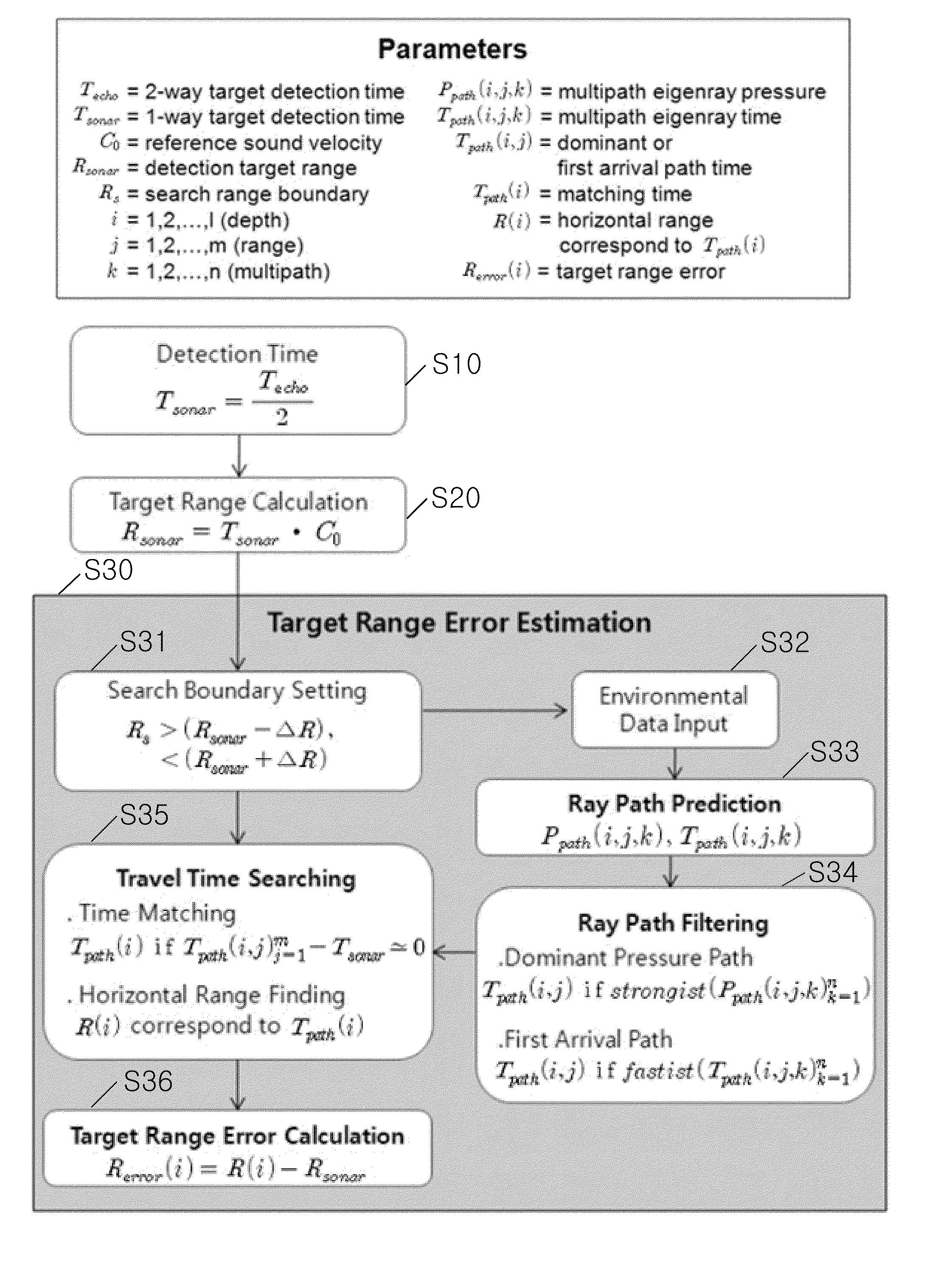
[0060]FIG. 3 is a flowchart showing an algorithm for estimating a target range error according to the present invention.

[0061]FIGS. 4 to 6 are graphs to which the algorithm of FIG. 3 have been applied.

[0062]FIG. 4 is a graph showing target ranges detected at each depth according to the present invention.

[0063]FIG. 5 is a graph showing range errors according to detection ranges according to the present invention.

[0064]Referring to FIG. 3, an algorithm for estimating a target range error comprises setting a search range boundary, predicting a ray path, filtering a ray path, searching a travel time, and calculating a target range error.

[0065]FIG. 3 shows an algorithm for applying substantial underwater environmental data by setting a target detection time and a detection target range detected by an active sonar as initial conditions, for predicting a path and an arrival time of a sound pulse transmitted from the active sonar to the target, and for estimating a target range error by sea...


PUM


Abstract

Disclosed is an active sonar system capable of estimating a direction and a range of a target by using a sound pulse. A target range error can be estimated by the active sonar system, by applying a principle that a sound pulse used to detect an underwater target with consideration of a vertical structure of a sound velocity in water is reflected and refracted through a multipath not a linear path.

Description

CROSS-REFERENCE TO A RELATED APPLICATION[0001]This application claims the benefit of and right of priority to Korean Application No. 10-2009-0103042, filed on Oct. 28, 2009, the contents of which is incorporated by reference herein in its entirety.FIELD OF THE INVENTION[0002]The present invention relates to a sonar (SOund NAvigation and Ranging) system capable of estimating a direction and a range of a target by using a sound pulse.BACKGROUND OF THE INVENTION[0003]A sonar system is an apparatus for estimating a direction and a distance (range) of an underwater target by using sound waves.[0004]Generally, sound waves (sound pulses or rays) are used to detect an underwater target such as a submarine. Even if the sound waves propagate with a low velocity, they are used to detect a distant target due to its less energy loss than that of an electric wave. Accordingly, a sonar system for detecting an underwater target by using sound waves for military purposes is being utilized.[0005]The ...

Claims


Application Information

Patent Timeline
IPC IPC(8): G01S15/00
CPCG01S15/101G01S7/52004G01S7/52001
Inventor PARK, JOUNG-SOONA, YOUNG-NAMKIM, YOUNG-GYU
Owner AGENCY FOR DEFENSE DEV
Why Eureka
Try Eureka