Technology for reducing circuit oscillations and ripple in a high-voltage power supply using a piezoelectric transformer

a piezoelectric transformer and high-voltage power supply technology, applied in the direction of corona discharge, process and machine control, instruments, etc., can solve the problems of deteriorating image quality, unnecessary circuit oscillation generation, and output ripple, so as to reduce unnecessary circuit oscillations

Active Publication Date: 2011-04-28
CANON KK
View PDF9 Cites 20 Cited by
  • Summary
  • Abstract
  • Description
  • Claims
  • Application Information

AI Technical Summary

Benefits of technology

[0007]The present invention has the feature that it may reduce unnecessary circuit osc

Problems solved by technology

Furthermore, since the drive frequency is changed, output ripple tends to occur in the constant voltage output of the piezoelectric transformer and unnecessary circuit oscillations tend to be ge

Method used


Image

  • Technology for reducing circuit oscillations and ripple in a high-voltage power supply using a piezoelectric transformer
  • Technology for reducing circuit oscillations and ripple in a high-voltage power supply using a piezoelectric transformer
  • Technology for reducing circuit oscillations and ripple in a high-voltage power supply using a piezoelectric transformer

Examples


example 1

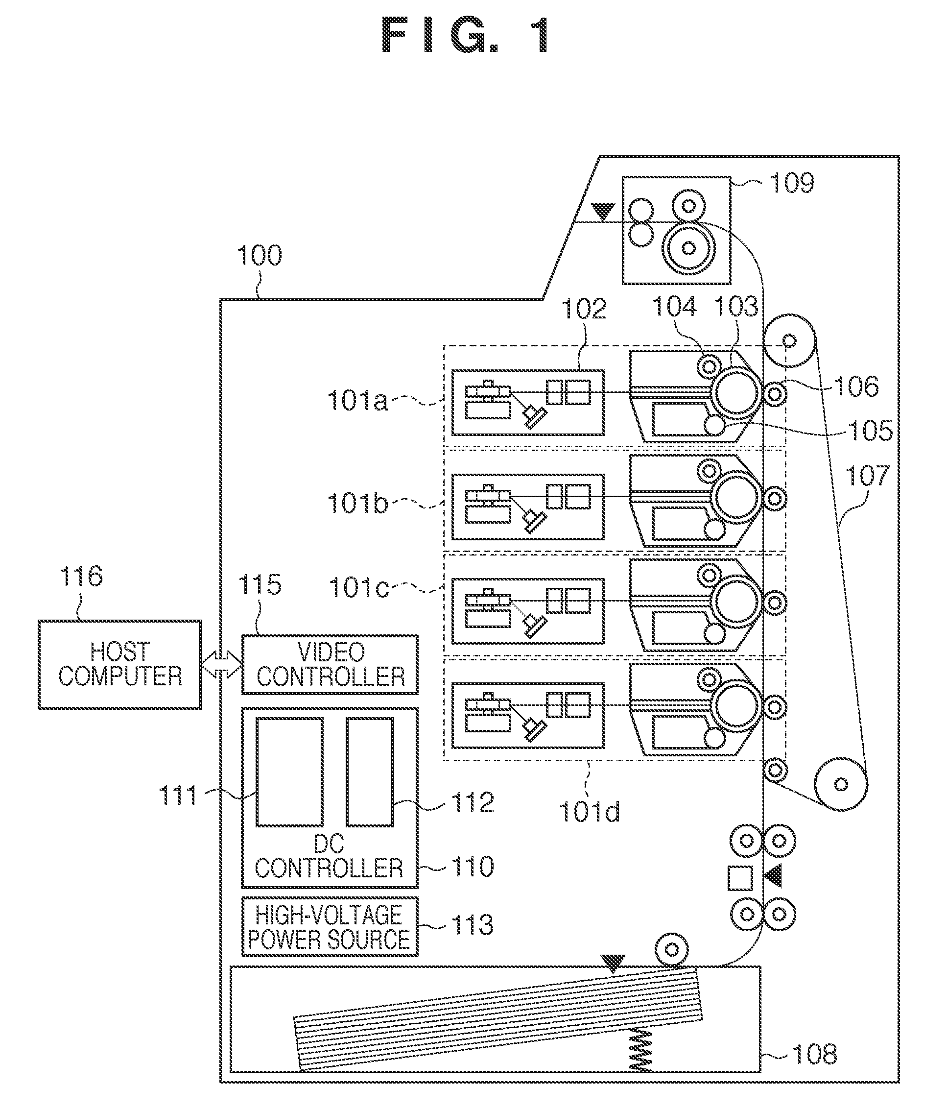
[0021]First, an overall configuration of a printer 100 is explained with reference to FIG. 1. The printer 100 is an example of an electrophotographic image forming apparatus to which a power supply in accordance with the present invention can be applied. The power supply of the present invention does not depend on the image forming method. Therefore, the present invention can be applied not only to electrophotographic printers, but to image forming apparatuses employing any kind of image forming method, such as inkjet printers. The printer 100 includes image forming parts 101a, 101b, 101c and 101d functioning as the image forming units for yellow (Y), magenta (M), cyan (C) and black (B), respectively. The image forming parts 101a to 101d have basically the same configuration. It should be noted that the index letters a to d attached to the reference numerals are omitted when explaining aspects that are common to all image forming parts. A charge roller 104 uniformly charges a photos...

example 2

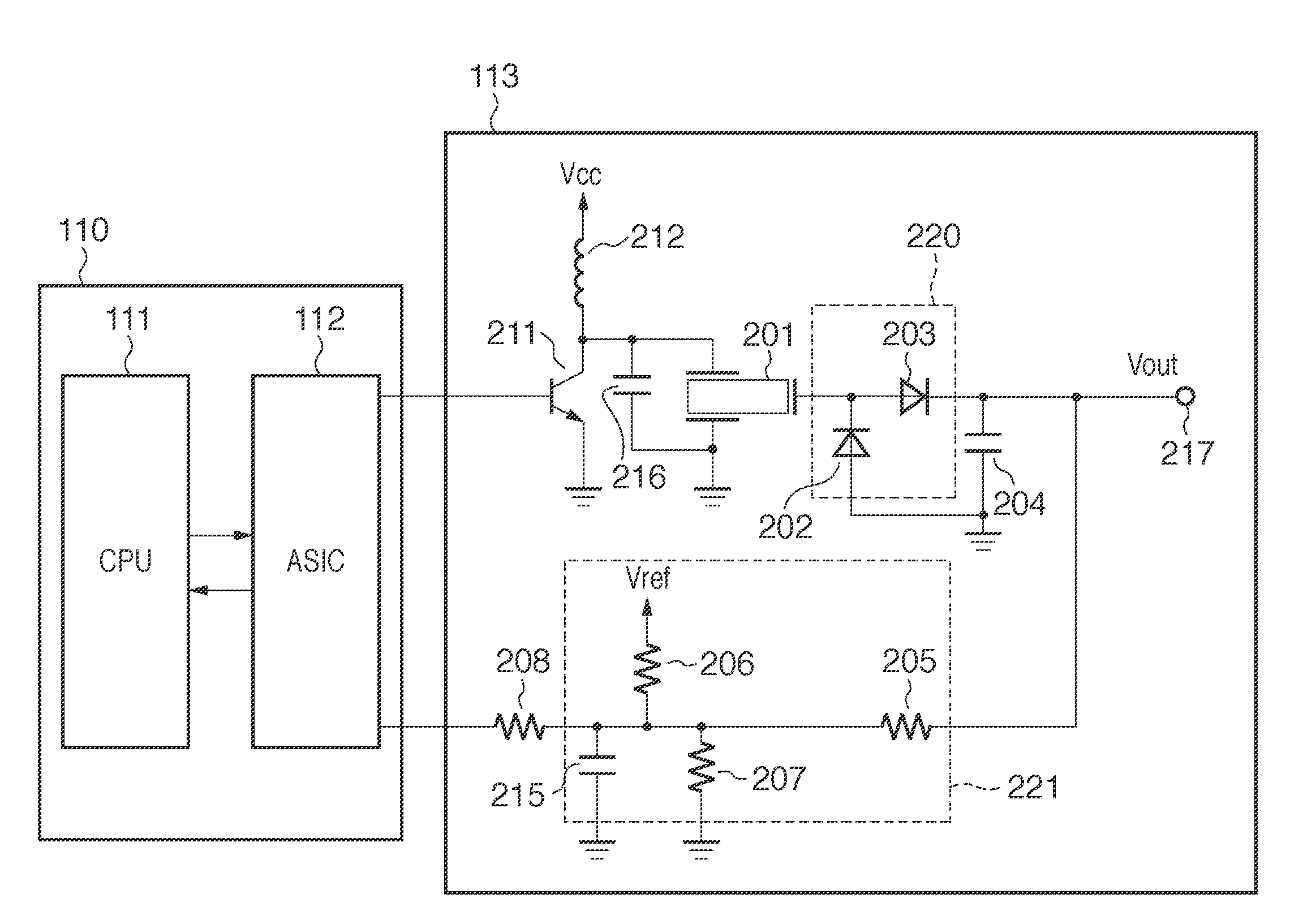
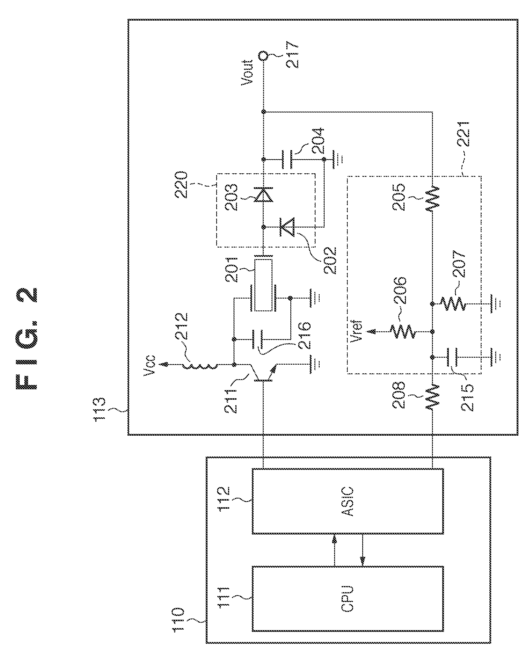
[0044]In Example 2,a filter part is provided that is connected to the voltage output side of the rectification part and reduces ripple included in the output voltage that is output from a rectification part. That is to say, as shown as an option in FIG. 5, a filter circuit 222 is provided between the control target and the output terminal 217. A fourth time constant T4, which is the time constant of the filter circuit 222 is adjusted such that the output voltage ripple (250 V) in the first time constant T1 (switching frequency of 16 kHz) can be sufficiently attenuated. More specifically, the control part and the filter part may be designed such that the first time constant T1 becomes smaller than the fourth time constant T4.

[0045]The following considers the case that the output ripple is to be attenuated to for example 1 / 100, as explained with reference to FIG. 7B. In this case, the frequency characteristics of the fourth time constant T4 of the control target should be such that th...


PUM


Abstract

A high-voltage power supply comprises the following components. A piezoelectric transformer outputs a voltage in accordance with a supplied drive frequency. A rectification part is connected to an output side of the piezoelectric transformer. A drive frequency generating part generates the drive frequency supplied to the piezoelectric transformer. A voltage detection part detects an output voltage of the piezoelectric transformer or the rectification part. A control part controls the drive frequency generating part such that a drive frequency corresponding to the output voltage detected by the voltage detecting part is generated. A first time constant, which is a time constant of the control part, is smaller than a second time constant, which is a time constant of a control target including the piezoelectric transformer and the rectification part. A third time constant, which is a time constant of the voltage detecting part, is smaller than the second time constant.

Description

BACKGROUND OF THE INVENTION[0001]1. Field of the Invention[0002]The present invention relates to a high-voltage power supply using a piezoelectric transformer and to an image forming apparatus using such a high-voltage power supply.[0003]2. Description of the Related Art[0004]In electrophotographic image forming apparatuses, it is necessary to provide a high-voltage power supply that generates voltages in excess of several hundred volts (high voltages), for example to apply a DC bias voltage to a transfer member. Conventional high-voltage power supplies have used wire-wound electromagnetic transformers, but in recent years, high-voltage power supplies have used piezoelectric transformers (piezoelectric ceramic transformers) as well.[0005]Japanese Patent Laid-Open No. 11-206113 discloses a high-voltage power supply including a voltage-controlled oscillator (VCO) generating a drive frequency that is input into a piezeoelectric transformer. The piezoelectric transformer has the feature...

Claims


Application Information

Patent Timeline
IPC IPC(8): G03G15/00G03G15/02H02M3/335
CPCG03G15/80H02M1/14H02M3/335H10N30/804
Inventor NAGASAKI, OSAMU
Owner CANON KK
Why Eureka
Try Eureka