According to the invention a paneling of a nacelle of a wind energy installation is created, in which in the installation position of the nacelle an upturned panel ceiling is provided. In the panel ceiling a hatch opening is formed or provided, which is formed or made so large, that components of the whole area of a drive
train of the wind energy installation can be removed upwards, or inserted from above into the nacelle through the hatch opening. Furthermore, the hatch opening is choosingly closable by a hatch cover.
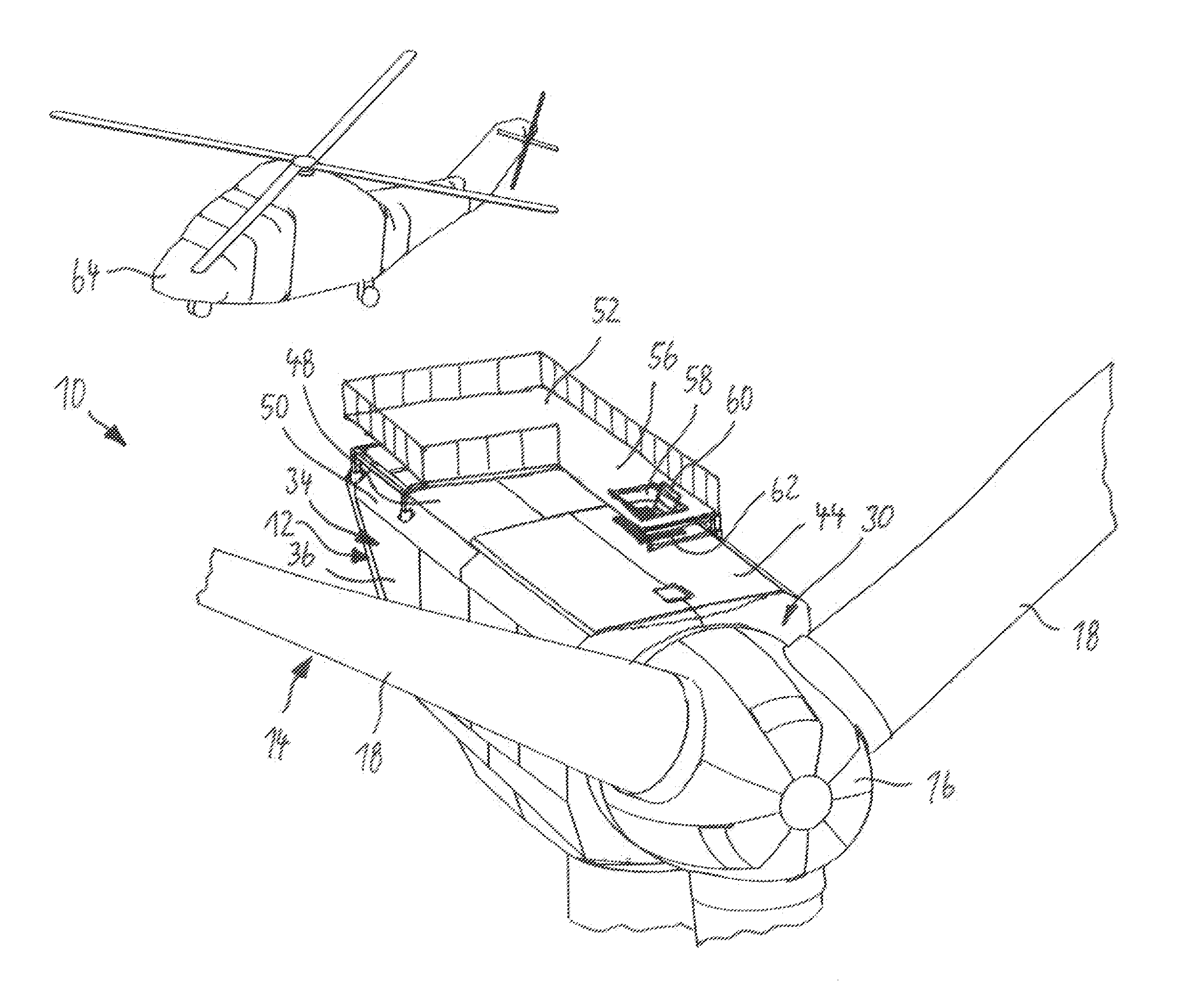
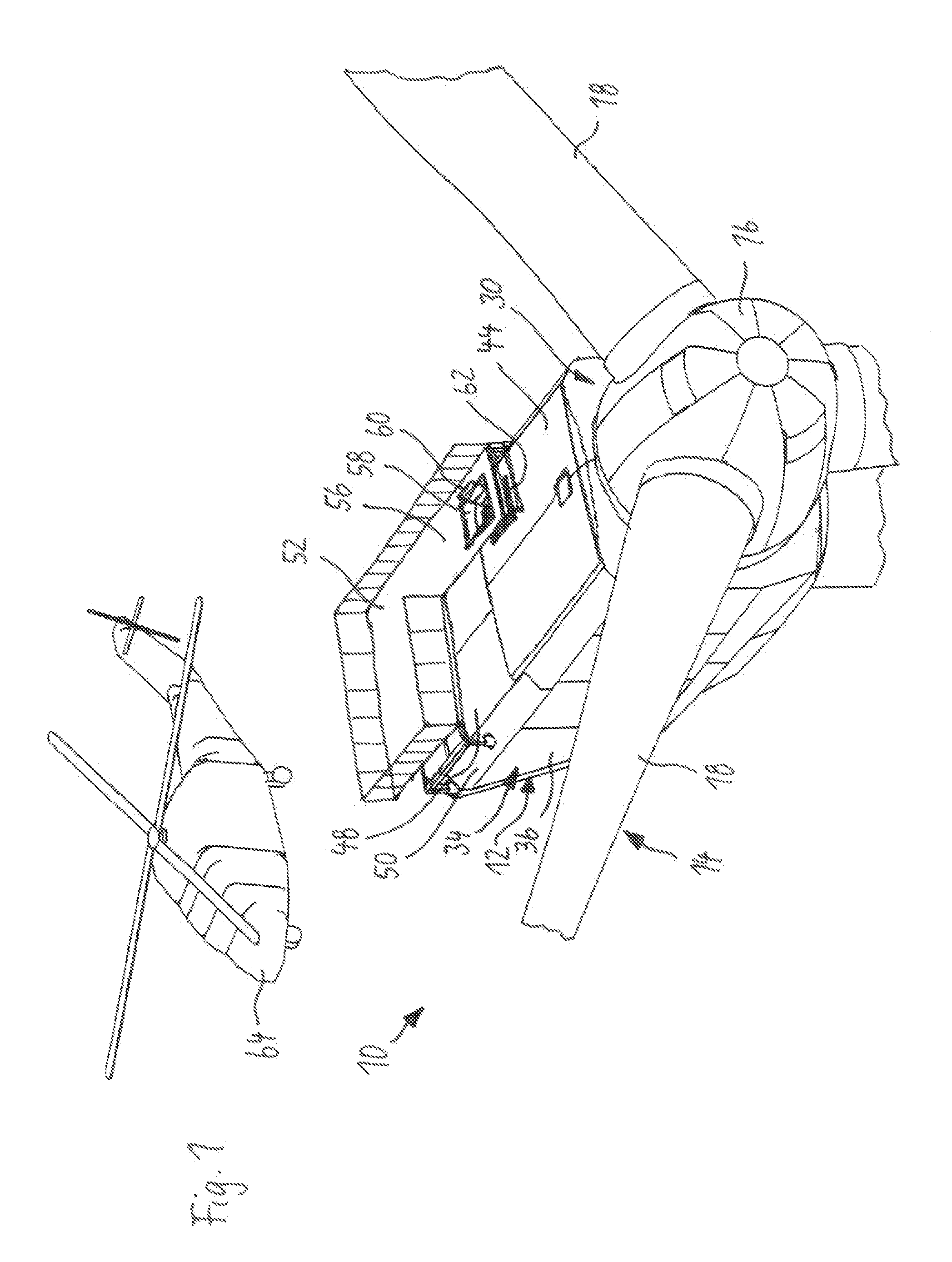
With regard to installing and maintaining components of a nacelle of a wind energy installation, the solution according to the invention is effected in a totally new way, as the components do not have to be hauled up from the bottom into the nacelle by a crane as in the case of conventional wind energy installations, but the components are inserted into the nacelle and also removed from it from above. This is preferably done from the air by means of a helicopter. The paneling of the nacelle of a wind energy installation according to the invention is in particular especially adapted, so that it can be approached by a helicopter, and thereafter, from the helicopter components can be inserted into the paneling of the nacelle but they can also be removed from there (in case of maintenance works).
Therefore, according to the invention, a particularly large hatch opening is provided on the upturned panel ceiling of the paneling of the wind energy installation, which can substantially be opened so wide, that it bridges or spans a large part of the panel ceiling. Such an
insertion of components, especially by means of a helicopter, is not possible with conventional (small-area) maintenance hatches, as they may also be partly provided on the upturned panel ceiling of wind energy installations at present.
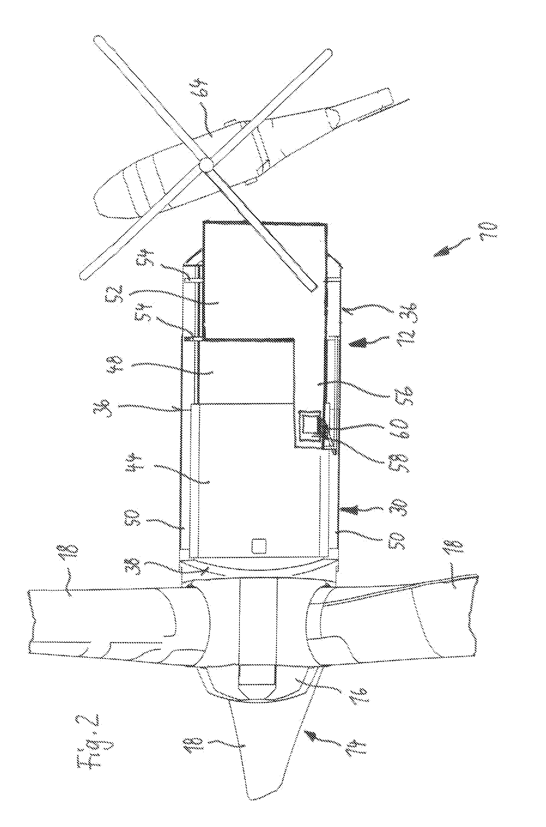
In known hatches on panelings of nacelles of a wind energy installation, generally the associated hatch covers can be flipped open, this means, they are arranged in a pivotable manner. In case of an advantageous improvement of the paneling or rather the wind energy installation according to the invention, the hatch cover is, however, slidable supported or beared. Therefore, this slidable bearing is especially advantageous because the hatch cover, according to the invention, is very extensive. With regard to the area exposed to wind during opening the hatch cover, the movable bearing is very advantageous. Furthermore, such a movable hatch cover is better fixed, when a helicopter approaches the nacelle.
It is also advantageous for safe opening and closing of the hatch cover according to the invention during harsh weather conditions, if this hatch cover is arranged and slidable on the outer face of the panel ceiling. Thereby, the hatch cover advantageously overlaps with the edge of the hatch opening, so that even during storms no rain or
snow can force its way into the interior of the paneling.
In case of another advantageous arrangement of the solution according to the invention, the hatch cover is about half the size of the panel ceiling, this means, it spans about half of the panel ceiling. With such a hatch cover, an optimal compromise between a coverable hatch opening, which is as large as possible, and at the same time a safe guidance and arrangement of the hatch cover during opening is created. The opened hatch cover is safely arranged on the residual half of the panel ceiling and only provides a small area exposed to wind there.
Another very advantageous use of the openable hatch cover according to the invention is further created by the fact, that on two side edges of the panel ceiling, which are arranged opposite each other, one rail per side edge is provided, on which in each case the hatch cover is slidable supported or beared.

