Data Communication and Object Localization Using Inductive Coupling

a data communication and object technology, applied in the field of electronic devices, can solve the problems of inability to combine optical noise resistance and ability, inability to detect and detect objects, and inability to detect objects, etc., and achieve the effect of reducing the cost of operation

Inactive Publication Date: 2011-04-28
3D ROBOTICS
View PDF9 Cites 53 Cited by
  • Summary
  • Abstract
  • Description
  • Claims
  • Application Information

AI Technical Summary

Benefits of technology

[0006]Apparatus and methods allow wireless communication between two objects based on inductive coupling. A first inductor coupled to a first object generates an inductive field in response to a transmit signal provided to the inductor. A second inductor coupled to a second object generates a signal responsive to the inductive field generated by the first inductor. An analog to digital convertor is coupled to the second inductor to receive the signal generated by the first inductor and convert it to a digital signal output. The output of the analog to digital convertor is processed by a processor coupled to the analog to digital convertor. The processor converts the digital signal output to a value indicative of a distance between the first physical object and the second physical object based on the strength of the received signal. The transmit signal can also can also encode arbitrary data, which the processor can interpret and act upon.

Problems solved by technology

However, no such schemes combine resistance to optical noise and the ability to localize different faces of physical objects down to centimeter resolution.
Infrared is in particular vulnerable to interference from other light sources, particularly the sun.
Higher frequency radio systems require sensitive antenna design and entail a great deal of labor to properly design and implement.
These solutions are thus relatively high cost.
These systems typically radiate signals fairly evenly in three-dimensional space, making it difficult to determine which face of a transmitting object is near another sensing object.
Further, sonic or ultrasonic solutions are particularly vulnerable to multi-path distortions and are expensive solutions, requiring more hardware (speaker, microphone) and generally more complex encoding and decoding algorithms.

Method used


Image

  • Data Communication and Object Localization Using Inductive Coupling
  • Data Communication and Object Localization Using Inductive Coupling
  • Data Communication and Object Localization Using Inductive Coupling

Examples


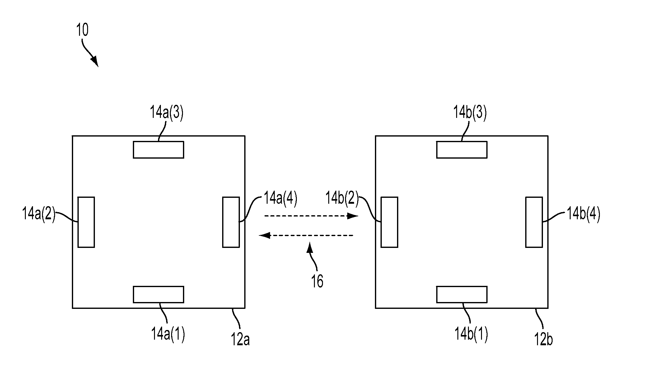
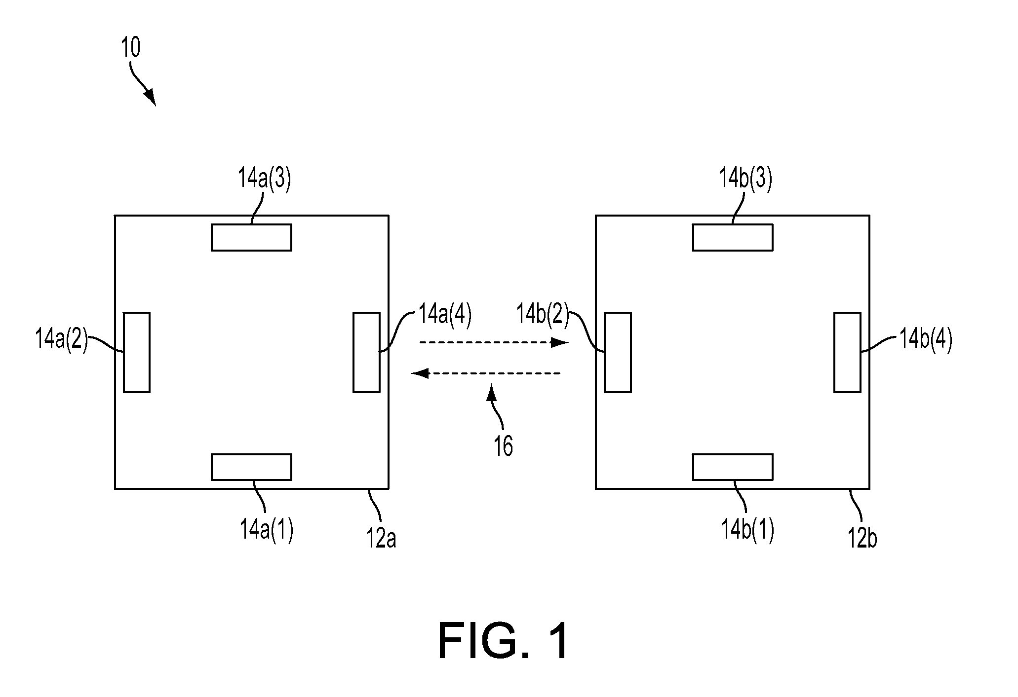
example communication

Configuration

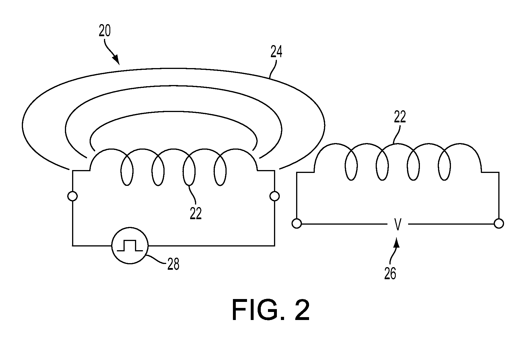
[0030]FIG. 2 illustrates one embodiment of a communication element 14 configuration for a transmitting sensor and receiving sensor. The configuration as illustrated may be referenced as a system 20. The system 20 is configured to include inductive coupling. In the system 20, a voltage signal 28 can be placed across an inductor 22 that can induce a voltage 26 in another nearby inductor 22, because the signal voltage 28 placed across the transmitting inductor creates a field 24 that can couple into the receiving inductor. By placing and removing an oscillating signal voltage 28 across a transmitting inductor in a pattern, messages of arbitrary data are created that can be received and interpreted by the receiving inductor. The presence or absence of a signal can be interpreted according to the specific application.

[0031]Turning to FIG. 3, it illustrates one embodiment of a communication element 14 of a physical object. In particular, the figure illustrates one embodiment ...


PUM


Abstract

An apparatus and method are disclosed for a software and hardware configuration that uses inductive coupling to allow a physical object to determine information describing another physical object. An inductor capacitor circuit acts as a transmitter as well as a receiver of inductive field. A voltage signal provided to an inductor in an object causes the inductor to generate inductive field received by another inductor in a second object. An object receiving inductive field from another object analyzes the inductive field to receive arbitrary data, including but not limited to data that can allow the receiving object to determine the identity of the object transmitting the inductive field. The object receiving the inductive field can also determine the distance between the receiving object and the transmitting object based on the strength of a signal generated by the inductive field.

Description

CROSS REFERENCES TO RELATED APPLICATIONS[0001]This application claims the benefit of U.S. Provisional Application No. 61 / 254,324, filed Oct. 23, 2009, which is incorporated by reference in its entirety.BACKGROUND[0002]1. Field of Art[0003]The disclosure generally relates to the field of electronics, particularly in the field of computing interaction.[0004]2. Description of Art[0005]A variety of wireless communication systems have been devised to solve a host of needs. However, no such schemes combine resistance to optical noise and the ability to localize different faces of physical objects down to centimeter resolution. Most systems are based on infrared light modulation or other higher frequency radio communication. Infrared is in particular vulnerable to interference from other light sources, particularly the sun. Higher frequency radio systems require sensitive antenna design and entail a great deal of labor to properly design and implement. These solutions are thus relatively h...

Claims


Application Information

Patent Timeline
Patent Type & Authority Applications(United States)
IPC IPC(8): H04B5/00
CPCH04B5/0043H04B17/27H04B5/0075H04B5/0081
Inventor KALANITHI, JEEVANMERRILL, DAVID
Owner 3D ROBOTICS
Why Eureka
Try Eureka