Control device for legged mobile body

a mobile robot and control device technology, applied in the direction of electric programme control, program control, instruments, etc., can solve the problems of inconvenience, inconvenient change of motion trajectory, etc., and achieve the effect of preventing the path length of the motion trajectory

Inactive Publication Date: 2011-04-28
HONDA MOTOR CO LTD
View PDF18 Cites 47 Cited by
  • Summary
  • Abstract
  • Description
  • Claims
  • Application Information

AI Technical Summary

Benefits of technology

[0021]Therefore, the desired motion determiner recognizes the predetermined type of stepped portion as a stepped portion having the gentle surface as the rising surface, and determines the leg motion parameter such that the contact between the stepped portion, including the gentle slope surface, and a leg of the robot will be avoided.
[0036]According to the fourth aspect of the invention, when increasing the height of distal end of the free leg in a motion trajectory by updating the leg motion parameter, the leg motion parameter is updated such that the landing position of the distal end of the free leg in the future is closer to the landing position immediately before the free leg leaves a floor than the landing position of the distal end of the free leg in the future specified by the leg motion parameter before updating. This arrangement makes it possible to prevent the path length of the motion trajectory of the distal end of the free leg from being extended by updating the leg motion parameter. As a result, a leg of the robot can be moved while restraining the moving velocity (angular velocity or the like) of a joint of a leg of the robot from becoming excessive while at the same time maintaining the traveling velocity of the robot approximately at a constant level before and after updating the leg motion parameter.

Problems solved by technology

In this case, however, the study by the inventor of the present application has revealed that the following inconvenience may occur.
However, there is a case where the motion trajectory of the distal end of the free leg relative to the actual floor deviates from the trajectory expected in the desired motion due to a slippage or the like of a supporting leg of the actual robot.
Further, in such a case, it may be inconveniently impossible to actually change the motion trajectory because of restrictions on the dynamics of the robot or the capabilities of actuators.

Method used


Image

  • Control device for legged mobile body
  • Control device for legged mobile body
  • Control device for legged mobile body

Examples


Embodiment Construction

[0062]The following will describe an embodiment of the present invention by taking a bipedal mobile robot as an example of a legged mobile robot.

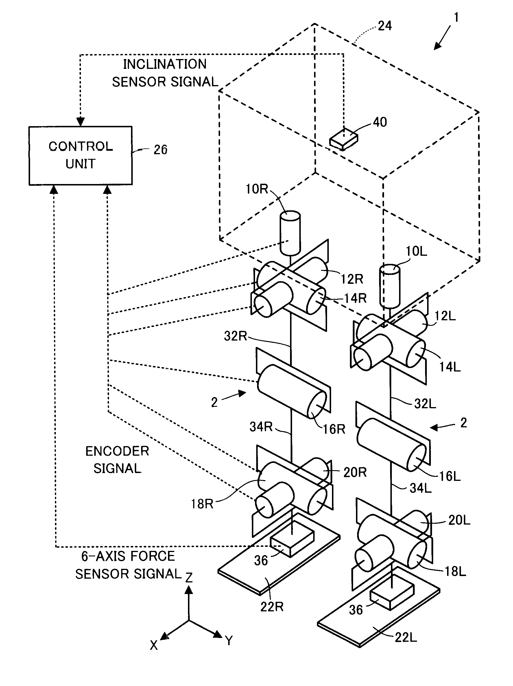
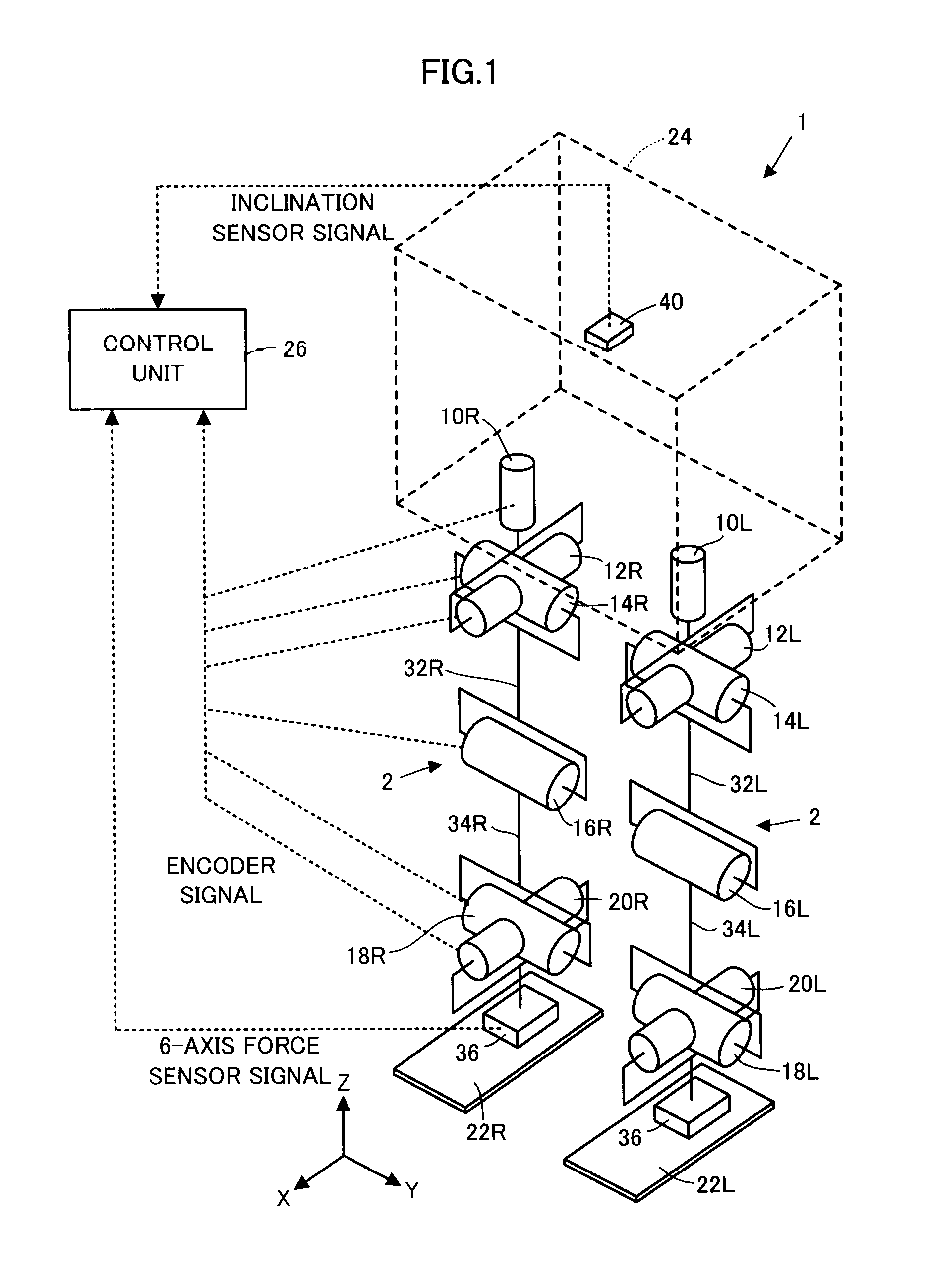
[0063]As illustrated in FIG. 1, a bipedal mobile robot 1 (hereinafter referred to simply as the robot 1) according to the present embodiment has a body 24 as a base body and a pair of right and left legs (leg links)2, 2 extended from the body 24 as a moving mechanism for moving the body 24 above a floor surface.

[0064]The body 24 is connected to the proximal end portions (upper end portions) of the two legs 2, 2 through the intermediary of a waist joint (hip joint), which will be discussed later, and is supported above the floor surface by one or both of the legs 2, 2 that are in contact with the ground.

[0065]The two legs 2, 2 share the same construction and each thereof has six joints. The six joints are a joint 10R or 10L for turning a waist (hip) (for the rotation in the yaw direction relative to the body 24), a joint 12R or 12L for turni...


PUM


Abstract

A desired motion determiner of a control unit of a legged mobile robot determines a leg motion parameter specifying the motion trajectory of a distal end of a leg of the robot on the basis of the information on a floor geometry of an environment in which the robot travels and a requirement related to a travel route of the robot, thereby sequentially determining the desired motion of the robot. A floor geometry information output unit which outputs floor geometry information to the desired motion determiner outputs floor geometry information in which a rising surface of a stepped portion of a predetermined type, the contact thereof with a leg of the robot should be avoided, has been shaped into a surface having a gentler slope than an actual rising surface. The desired motion determiner determines the leg motion parameter such that the leg will not come in contact with the stepped portion having the shaped rising surface.

Description

BACKGROUND OF THE INVENTION[0001]1. Field of the Invention[0002]The present invention relates to a control device for a legged mobile robot, such as a bipedal robot.[0003]2. Description of the Related Art[0004]For a legged mobile robot which moves by the motions of a plurality of legs provided such that the legs extend from a base body, a control technique that allows a desired gait including a desired motion of the robot to be sequentially generated in real time and to control the motion of the robot so as to make the actual gait of the robot follow the desired gait has been proposed by the applicant of the present application in, for example, Japanese Patent No. 3269852, Japanese Patent No. 4246638, and Published PCT International Application WO2002 / 040224.[0005]To sequentially generate desired motions of the robot in real time while controlling the motion of the robot as described above, it is necessary to supply the information on a floor geometry, which indicates the floor geom...

Claims


Application Information

Patent Timeline
Patent Type & Authority Applications(United States)
IPC IPC(8): B25J9/18
CPCB62D57/032
Inventor YOSHIIKE, TAKAHIDETAKEDA, MASANORIKURODA, MITSUHIDEWATABE, TOMOKI
Owner HONDA MOTOR CO LTD
Why Eureka
Try Eureka